Article citation information:
Mantič, M., Kuľka, J., Kopas, M., Faltinová, E., Petróci, J. Special device for continuous deceleration of freight cableway trucks. Scientific Journal of Silesian University of Technology. Series
Transport. 2016, 91, 89-97. ISSN:
0209-3324.
DOI: 10.20858/sjsutst.2016.91.9.
Martin MANTIČ[1],
Jozef KUĽKA[2],
Melichar KOPAS[3],
Eva FALTINOVÁ[4],
Ján PETRÓCI[5]
SPECIAL DEVICE FOR CONTINUOUS DECELERATION OF freight CABLEWAY TRUCKS
Summary. This paper is focused on the design of an auxiliary braking device for freight
cableway trucks. The device provides continuous deceleration for the trucks
before they arrive at the unloading station. It presents an alternative to
manual deceleration, which poses safety hazards and is therefore a less
suitable option. The design distinctly accommodates the spatial disposition at
the unloading station and involves minimal interventions to the existing
steel structure. Above all, it aims to increase safety by eliminating the need
for human input in the process of decelerating the trucks before they are
emptied. The proposed design solution was successfully applied in a real
operation.
Keywords: cableway, truck, friction brake,
braking force, design solution
1. INTRODUCTION
This paper focuses on the construction
of an auxiliary device for material cableways. Cableways convey material in trucks
pulled by a wire rope. Depending on whether the trucks move along ground rails
or taut cables above the ground, either aerial cableways or cable railways are
involved. Aerial cableways transport people and material over great distances
or in an impassable terrain. The trucks move along taut cables suspended
in air. The diversity of the terrain bears no influence on the function of the
cableway, such that the space under it can be otherwise used. Aerial cableways
can span valleys, mountains, rivers, roads and buildings. They are suitable for
conveying both bulk material and unit loads [1, 8]. According to the construction
type, there are bi-cable cableways, with a track cable and a haul rope, and
mono-cable cableways, with a single cable used for both support and propulsion.
Either circular or shuttle cableways according to the direction of movement [3,
4, 5]. Taking into consideration the above-mentioned facts concerning the
cableway’s construction, it is possible to say that one of the most important
constructional parts of the cableway is simply the cable, which is
designed as a steel wire rope. The steel wire rope is usually wound from six
strands or it consists only of one strand and is constructed by laying several
strands around a core. Two kinds of steel wire rope are applied in the case of a
bi-cable cableway, i.e., the single-strand rope together with the six-strand
rope. The single-strand rope fulfils a supporting function, while the main task
of the six-strand rope is traction [6, 7].
The
device on which this paper focuses involves a material cableway in a cement
plant, which currently specializes in producing ground limestone and dolomites.
It conveys limestone lumps from the quarry to the lime plant. It is a material
aerial bi-cable circular system with a detachable grip for the truck. The
concept behind the aerial bi-cable circular cableway is illustrated in the
diagram in Fig. 1.
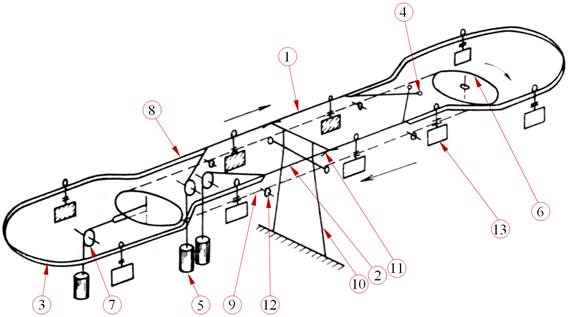
Fig. 1. Diagram of the aerial
bi-cable circular cableway [2]
1 – track cable on the loaded
side, 2 – track cable on the unloaded side, 3 – rail, 4 – track cable
anchorage, 5 – track cable tensioning, 6 – drive, 7 – haul rope tensioning, 8 –
attachment point,
9 – haul
rope, 10 – support, 11 – saddle, 12 – haul rope sheave, 13 – load truck
The cableway was commissioned in
1948 and overhauled in 2005. Its transport capacity is 60 t/h. The bottom
station is located at 370 m above sea level, while the top station is located at
660 m above sea level, meaning the cableway rises 290 m. There are 44 trucks,
which service the cableway.
2. CURRENT SITUATION
The design presents a solution for
the cableway’s unloading station. When the trucks are detached from the haul
rope, they roll along the gravity rail at 2.5 m/s by their weight to the point
where they are decelerated in order to be emptied. Once unloaded, they roll by
inertia to the point where they are reattached to the haul rope.
The trucks used to be decelerated by
friction brakes, which created down pressure on the truck wheels between
the rail and the steel load-carrying structure at the unloading station (Fig.
2).
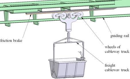
Fig. 2. Deceleration of a truck by
friction brake
A wooden block was used as a
friction element. This deceleration mode, however, was not effective enough,
due to rapid wear to the braking element, as well as frequent damage (wood
chipping) caused by the impact of moving trucks.
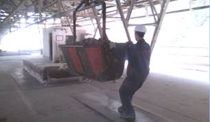
Fig. 3. Manual truck deceleration
Alternatively, the operating staff
would decelerate the trucks manually before they were emptied (Fig. 3). This
solution was effective, but it was inadequate due to the safety hazards it
posed for the operators.
To eliminate these shortcomings, the
operation has demanded a new conceptual solution design. It has to ensure the trucks
are decelerated by a mechanical braking system without human input. The
operating staff would only be responsible for emptying the decelerated trucks.
Empty trucks must retain enough speed to keep rolling along the gravity rail to
the point where they are reattached to the haul rope.
3. SOLUTION DESIGN
It is necessary to decelerate the trucks detached from the haul rope
from 2.5 m/s to 0.5 m/s. The new solution assumes minimal interventions to the
existing steel structure at the unloading station. It also needs to allow
for the spatial constraints associated with its installation. The engineering
design of the new solution is based on a principle of continuous deceleration
of the trucks by using rotating wheels. Each wheel has a different frequency of
rotation achieved by the interconnected toothed belts and reduction gears.
Deceleration is ensured, due to the friction occurring between the truck wheels
and the set of rotating wheels as their speed decreases (Fig. 4). Questions concerning dynamic phenomena, which occur during acceleration
or braking, and mechanical losses are analysed in [9, 10, 11].
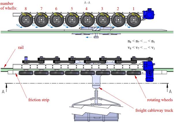
Fig.
4. Block diagram of the braking system
The toothed belts with the reciprocal meshing factor of 1.25 ensure the rotary
motion of the wheels (Fig. 6). The meshing achieves gradual reduction in
shaft revolutions (Fig. 5) and, consequently, in the circumferential speed from
2.5 m/s at the front wheel to approximately 0.5 m/s at the back wheel
(Fig. 6).
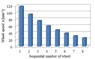
Fig. 5. Speeds of rotating
wheels
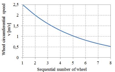
Fig. 6.
Circumferential speeds of brake wheels
The calculation of the necessary power is based on the force ratios (Fig.
7), where FN denotes the contact force, R denotes the wheel radius,
v denotes the speed, Fob denotes the circumferential force, e
denotes the arm of the rolling resistance, rč
denotes the arm of the pivot’s resistance, and Fčt denotes the
pivot’s frictional resistance.
|
|
|
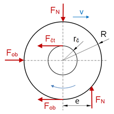
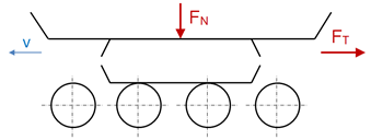
Fig. 7. Force ratios
According to the
distribution of forces illustrated in Fig. 7, the circumferential force Fob
can be formulated as in Equation (1) and the required power as in Equation
(2).
![]() (1)
(1)
![]() (2)
(2)
where hc is the total efficiency of the whole assembly.
In
terms of its construction, the braking system is made of braking segments (Fig.
8) with an alternating arrangement of toothed belts, which provide continuous
and reciprocal speed reduction.
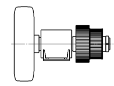
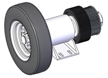
Fig. 8. View of
the braking element
The
braking segments are located on adjustable support brackets (Fig. 9), where a drive
(a geared motor) is also mounted. Tensioning of the belts between the individual belt pulleys is individually
designed for each of the braking segments by means of the tensioning screws.
Application of commercially accessible belt stretchers was impossible with
regard to the dimensional dispositions.
The
bracket accommodates the space disposition of the existing structure, as well
as the options available for its set-up and simple installation. The down
pressure for the brake is designed in order to be exerted by the sliding
mechanism in the support bracket, as well as by pumping up the tires.
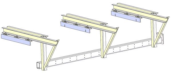
Fig. 9. Support
bracket of the braking system
Fig. 10
presents the overall view of the conceptual solution for the braking system
mounted on the existing steel structure.
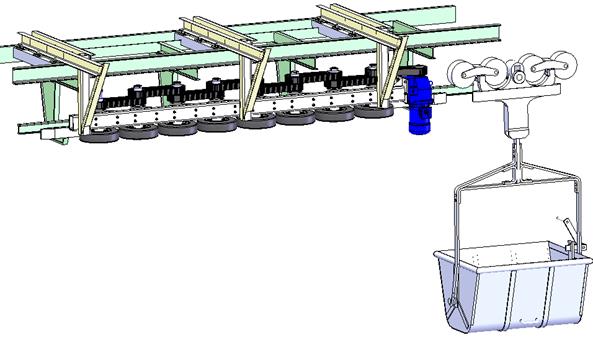
Fig. 10.
Solution model of the braking system
The braking system was installed
experimentally in a real operation for testing the whole equipment, as
well as for tuning the operational parameters and possible constructional
modifications. The ideal approach of the cableway truck towards the first
braking wheel is important with regard to the elimination of undesirable
vibrations in the construction.
This special braking system is now
being utilized successfully during discharging of the cableway trucks within
the discharging station of the freight cableway.
4. CONCLUSION
The designed braking
device has sought to increase the level of safety for the operators as they
empty the freight cableway trucks. The system is designed to operate with eight
braking segments under continuous drive. Continuous deceleration of the
circumferential speed of the presser wheel in the braking system ensures speed
reduction for the incoming trucks at the unloading station. The next step will focus
on an engineering design for the discharging system, which will ensure the
complete elimination of human input in this section of the cableway in the near
future.
This
paper was elaborated in the framework of the following projects: VEGA 1/0198/15
– research on innovative methods for emission reduction of driving units used
in transport vehicles and optimization of active logistic elements in material
flows in order to increase their technical level and reliability; and KEGA 021TUKE–4/2015 – development of
cognitive activities focused on innovations in educational programmes in the discipline
of engineering, as well as building and modernizing specialized laboratories
specified for logistics and intra-operational transport.
References
1.
Dražan F., K. Jeřábek.
1979. Manipulace s materiálem. [In
Czech: Materials handling.] Prague:
SNTL/ALFA.
2.
Dražan F., L. Kupka
et al. 1966. Transportní zařízení. [In
Czech: Transportation equipment]. Prague:
SNTL/SVTL.
3.
Remta F. 1953. Visuté lanové dráhy. [In Czech: Aerial ropeways]. Prague: SNTL.
4.
Cvekl Z., F.
Dražan et al. 1976. Teoretické základy
transportních zařízení. [In Czech: Theoretical
foundations of transport equipment]. Prague: SNTL/ALFA.
5.
Jasaň V., J. Košábek,
N. Szuttor, 1989. Teória dopravných
a manipulačných zariadení. [In Slovak: Theory of transport and handling equipment].
Bratislava: ALFA.
ISBN: 80-05-00125-8.
6.
Boroška
J., J. Hulín, O. Lesňák. 1982. Oceĺové
laná. [In Slovak: Steel ropes]. Bratislava:
ALFA.
7.
Costello G. A.
1997. Theory of Wire Rope. New York: Springer-Verlag.
ISBN 0-387-98202-7.
8.
Pajer G., H. Kuhnt,
F. Kurth. 1988. Stetigförderer. [In
German: Continuous conveyors]. Berlin:
VEB Verlag Technik. ISBN: 3-341-00452-1.
9.
Łazarz B., G.
Wojnar, H. Madej, P. Czech. 2009. Evaluation of gear power losses from
experimental test data and analytical methods. Mechanika 6(80): 56-63.
ISSN 1392-1207.
10.
Konieczny Ł., R. Burdzik,
J. Warczek, P. Czech, G. Wojnar, J. Młyńczak. 2015. Determination of the effect
of tire stiffness on wheel accelerations by the forced vibration test method. Journal of Vibroengineering 17(8):
4469-4477.
ISSN: 1392-8716.
11.
Sága M., R. Bednár,
M. Vaško. 2011. “Contribution to modal and spectral interval finite element analysis”.
In 10th International
Conference on “Vibration Problems ICOVP”:
269-274. Edited by Náprstek J., J. Horáček, M. Okrouhlík, B. Marvalová, F.
Verhulst, J. T. Sawicki. Liberec, Czech Republic.
Dordrecht: Springer Science+Business Media B.V. ISBN 978-94-007-2068-8.
Received 02.11.2015; accepted in revised form 29.03.2016
![]()
Scientific Journal of Silesian University of
Technology. Series Transport is licensed under a Creative Commons
Attribution 4.0 International License