Article citation information:
Kopas, M., Kuľka, J., Mantič, M., Faltinová, E.,
Bigoš, P. Increasing durability in steel
wire rope installed in special transport equipment. Scientific Journal of Silesian University of Technology. Series
Transport. 2016, 91, 71-80.
ISSN: 0209-3324.
DOI: 10.20858/sjsutst.2016.91.7.
Melichar KOPAS [1],
Jozef KUĽKA[2],
Martin MANTIČ[3],
Eva FALTINOVÁ[4],
Peter BIGOŠ[5]
INCREASING DURABILITY IN STEEL WIRE ROPE INSTALLED IN SPECIAL TRANSPORT
EQUIPMENT
Summary. In this paper, special
transport-handling equipment is presented for the purpose of pushing wagons in
a trans-shipment facility. During operations, the rotary tilter device, which
is an integrated part of the trans-shipment process, leads to excessive wear of
the steel wire rope used for pushing wagons by means of a pusher system.
Therefore, the main task was to propose a suitable design modification of the
given pusher system in order to eliminate excessive wear of the rope and, in turn,
to prolong operational durability for this steel wire rope, as well as for the
whole technical system.
Keywords:
steel rope durability, wagon, tilter, pusher system, driving station
1. INTRODUCTION
Possible causes of
rope damage have been addressed by certain authors [5,6,7,8]. In paper [9], the author describes a mathematical
and geometric model for computer simulation of wire ropes, while [10] presents friction
losses in gearboxes are analysed with regard to their efficiency. For users of
steel wire rope, durability is the most important attribute, as it affects the
economy of the device with the steel cable as a part. Of the many factors
affecting the service life of wire rope, loading is very important. The size of
loading is one of the variables, by which we characterize the device. A rope bears
static, dynamic and bending forces during its operation. Their calculation is
quite simple. If we know the static load of the rope, we can calculate the
specific load of the rope, as well as the pressure between the rope and the
sheave (i.e., drum or pulley). On the basis of the calculated values and by
comparing them with table values, we can assume, with a certain level of probability,
the achievement of a certain durability or service life.
The durability of the rope
is affected by many factors, which can be divided into the
following three basic groups [1]:
Ø production (rope design, quality of production, cross section and strength of wires etc.)
Ø service (maintenance, environment,
methods of operation etc.)
Ø factors influenced by a device
(material and shape of the
grooves of a pulley, diameter and angle of wrap
around the support and deflection rollers, angle of attack of the rope to a pulley etc.)
Individual factors do not act alone.
In other words, during the operation of the rope, current and mutual
interaction of several factors occur. From the static load of the rope, it is
possible to calculate its specific load, as well as the pressure between the
rope and pulley (sheave, drum). From calculated values of these variables, it
is possible to assume the achieved durability of the steel wire rope in the corresponding
device. Static load of the rope is determined by the sum of all loadings of the
devices working together on that rope, including its own weight, if the rope is
moving in a vertical plane. In addition to this calculation, it is
possible to obtain loading values by using different measuring devices (load
limiters, scales, load cells), which show the real values of the load at
the specific time. From these measurements, we can find that forces in the rope
are not constant, but change during the working cycle.
The change of load size is caused by
the action of dynamic forces arising from different stimuli, such as:
· resistance against the load movement due
to passive resistance
·
acceleration or deceleration of the load movement at the start or finish of lifting equipment
· longitudinal and transverse oscillations of wire rope
2. ANALYSIS AND
CALCULATION OF SPECIAL PUSHER SYSTEM
The maximum rope tensile force ![]() is determined
according to the real value of the operational load and using the ratio
value of block and tackle. The next step involves the calculation of the rope
diameter, after which the mean radius of the rope drum is calculated.
is determined
according to the real value of the operational load and using the ratio
value of block and tackle. The next step involves the calculation of the rope
diameter, after which the mean radius of the rope drum is calculated.
According to the STN ISO 4308/1 (STN
27 0050), the rope diameter d (mm) is obtained by using the following relation:
![]() ,
(1)
,
(1)
where![]() is the coefficient of rope selection and
is the coefficient of rope selection and![]() is the maximum loading of the rope (in N), which is obtained
by means of the following coefficients:
is the maximum loading of the rope (in N), which is obtained
by means of the following coefficients:
· nominal operational loading
· weight of the pulley block
· block and tackle ratio value
· efficiency of the block and tackle
ratio value
The minimal value of
the load carrying capacity is:
![]() ,
(2)
,
(2)
where  is the maximal loading of the rope (in N), while
  is the minimal value
of the rope safety coefficient, which is selected according to the classification
of the hoisting mechanism (from M1 to M8, Table 3).
is the minimal value
of the rope safety coefficient, which is selected according to the classification
of the hoisting mechanism (from M1 to M8, Table 3).
The minimal value of the rope drum
diameter and the individual rope pulley diameters are calculated from the
minimal value of the rope diameter (1), using the values![]() ,
, ![]() and
and ![]() , with regard to the classification of the given hoisting
mechanism (see Table 1):
, with regard to the classification of the given hoisting
mechanism (see Table 1):
![]() , (3)
, (3)
where ![]() is the mean diameter of the drum (mm),
is the mean diameter of the drum (mm), ![]() is the mean diameter
of the pulley (mm),
is the mean diameter
of the pulley (mm),![]() is the mean diameter of the balancing pulley
(mm),
is the mean diameter of the balancing pulley
(mm), ![]() is the minimal diameter of the rope (mm),
is the minimal diameter of the rope (mm),![]() is the selective coefficient for the drum,
is the selective coefficient for the drum, ![]() is the selective coefficient for the pulley, and
is the selective coefficient for the pulley, and![]() is the selective coefficient for the balancing pulley.
is the selective coefficient for the balancing pulley.
Table 1
Selective coefficients![]() ,
,![]() ,
, ![]()
|
Classification of mechanism |
Drums
|
Pulleys
|
Balancing pulleys
|
|
M 1 |
11.2 |
12.5 |
11.2 |
|
M 2 |
12.5 |
14.0 |
12.5 |
|
M 3 |
14.0 |
16.0 |
12.5 |
|
M 4 |
16.0 |
18.0 |
14.0 |
|
M 5 |
18.0 |
20.0 |
14.0 |
|
M 6 |
20.0 |
22.4 |
16.0 |
|
M 7 |
22.4 |
25 |
16.0 |
|
M 8 |
25.0 |
28 |
18.0 |
At the same time, the rope tensile force is also the circumferential force,
which is acting on the mean radius of the drum; in turn, the torque on the drum
shaft is also known. Selection of the driving system and the total transmission
ratio are determined with regard to the rope tensile force and the hoisting
speed.
However, it is necessary to
calculate the number of the rope windings on the drum, in order to create the
required friction force between the rope and the drum.
There is well-known relation defined
according to Euler, i.e.,![]() , which describes a phenomenon of the belt friction, which
occurs between the rope and the drum. The force value
, which describes a phenomenon of the belt friction, which
occurs between the rope and the drum. The force value ![]() is the
input tensile force in the rope (tension on the pulling side), the force value
is the
input tensile force in the rope (tension on the pulling side), the force value ![]() is the output tensile
force in the rope (tension on the resisting side),
is the output tensile
force in the rope (tension on the resisting side),![]() is the coefficient of friction between the rope
and drum,
is the coefficient of friction between the rope
and drum,![]() is the wrap angle around the rope drum and
is the wrap angle around the rope drum and![]() is the base of the natural logarithm.
is the base of the natural logarithm.
Table 2 offers information about the
required number of rope windings on the drum (or the wrap angle) with
regard to the ![]() values.
values.
Table 2
Required number of rope windings for various
coefficients of friction
between the rope and the drum
|
Values |
|||
|
Number of windings |
f = 0.13 |
f = 0.15 |
f = 0.18 |
|
0.5
(α = π) |
1,503 |
1,602 |
1,758 |
|
1.0
(α = 2π) |
2,260 |
2,565 |
3,090 |
|
2
(α = 4π) |
5,105 |
6,583 |
9,550 |
|
3
(α=6π) |
11,534 |
16,890 |
29,512 |
|
4
(α=8π) |
26,062 |
43,331 |
91,202 |
|
5
(α=10π) |
58,884 |
111,170 |
281,840 |
|
6
(α=12π) |
133,040 |
285,230 |
870,960 |
Table
3
![]() values
values
|
Classification of mechanism |
M 1 |
M 2 |
M 3 |
M 4 |
M 5 |
M 6 |
M 7 |
M 8 |
|
Value of |
2.5 |
2.5 |
3.0 |
3.5 |
4.0 |
4.5 |
5.0 |
5.0 |
The specific load of steel wire rope
is a relatively simple and characteristic value for steel wire ropes. It allows
for the determination of working conditions of the rope and its load. The specific
load of the rope is defined [2] as the ratio between the maximum static load of
the rope and its cross section:
![]() ,
(4)
,
(4)
where![]() is the maximum static load of steel wire rope (in N),
while
is the maximum static load of steel wire rope (in N),
while ![]() is the bearing cross section
of wire rope (in m2).
is the bearing cross section
of wire rope (in m2).
Figure 1 [2] illustrates the course
of dependence in relation to the specific load of steel wire rope on fatigue
cycles, which represent the durability or life of steel wire rope.
Fig. 1. Curve of specific load of steel wire rope
Pressure between the rope and sheave
also affects the durability of steel wire ropes and is dependent on the load of
the rope. The size of the maximum pressure, with which the rope acts on the
sheave (pulley, drum), can be calculated according to the following formula:
![]() (5)
(5)
where![]() is the maximum pressure, with which the
rope acts on the sheave (pulley, drum) (in Pa),
is the maximum pressure, with which the
rope acts on the sheave (pulley, drum) (in Pa),
![]() is the maximum static load of steel wire rope (in N),
is the maximum static load of steel wire rope (in N), ![]() is the diameter of the sheave (pulley, drum)
(in m), and
is the diameter of the sheave (pulley, drum)
(in m), and![]() is the diameter of the wire rope (in m).
is the diameter of the wire rope (in m).
According to the above-mentioned
formula, it can be seen that the size of pressure between the rope and sheave
at a given static load can be reduced by increasing the diameter of the sheave
(pulley, drum) and the diameter of the rope. That said, significantly increasing
the diameter of the rope from the point of view of stress is not particularly
important. The ratio between ![]() and d, which is
defined according to individual lifting and towing equipment, ranges from 25 to
100. The recommended pressure values are given in Table 4.
and d, which is
defined according to individual lifting and towing equipment, ranges from 25 to
100. The recommended pressure values are given in Table 4.
Currently, the Eastern Slovak
Trans-shipment Yards (ESTY) provide trans-shipment for over 90% of raw
materials and goods imported to Slovakia by rail from Eastern Europe and Asia
[3]. The significance of the ESTY’ status enhances their uniqueness as the
largest of their kind, offering a comprehensive range of services from broad
gauge (BG) (1,520 mm) to normal gauge (NG) (1,435 mm), which is applicable
to Slovakia.
The crucial technological device for reloading
involves the rotary tippler wagon on BG track with a load capacity of 100 t (see
Figure 2.). Tippler is a rotating device in the shape of a keg, into which the
wagons are inserted. After stopping the carriage and fixing the wagon, the
whole tippler turns upside down around the longitudinal axis of the wagon.
After tipping the wagon and stabilizing the tilter in the basic position, the wagon
is then pulled from the tilter by a pusher located on the high ramp at Facility
III (see Figure 3).
Table 4
Pressure in the groove drive roll (MPa) [4]
|
Lifting |
Rope speed (ms-1) |
||||||||
|
0.3 |
0.5 |
0.7 |
1.0 |
1.4 |
2.0 |
2.8 |
4.0 |
Over 4.0 |
|
|
I |
8.2 |
7.2 |
6.3 |
5.7 |
5.6 |
4.2 |
3.8 |
3.5 |
3.5 |
|
II |
8.9 |
8.0 |
7.1 |
6.5 |
5.9 |
5.2 |
4.8 |
4.5 |
- |
|
III |
9.6 |
8.6 |
8.0 |
7.3 |
6.6 |
6.2 |
- |
- |
- |
|
IV |
10.2 |
9.4 |
8.8 |
8.2 |
7.7 |
- |
- |
- |
- |
I - duty cycle over 40%
or the number of cycles greater than 90/hour
II - duty cycle up to 40% or the number of cycles up to 90/hour
III - duty cycle up to 40% or the number of cycles up to 60/hour
IV - duty cycle up to 20% or the number of cycles up to 30/hour
3. DESIGN MODIFICATION OF TRANSPORT-HANDLING
EQUIPMENT
After turning the tilter, the
contents of the wagon will be flown through a steel grate into the tray (a slip
hopper), the volume of which should ensure retention of the material (it has
the volume of about two BG wagons, i.e., approximately 134 t of transported
material). Two mills (drum crushers) are installed in the area above
the grate, which will be put into operation if the ore is frozen or creates a
larger chest, such that, by passing over the entire grid, seized lumps or
insufficiently unfrozen material are crushed. The bottom tray is finished with
four scraper belt conveyors, which evenly shovel spilled material from wagons. Positioned
on the conveyor belt is a continuous scale for indicative weighing of
interlaced material. The weighed amount of the interlaced material from the
conveyor belt passes through the separator of items, onto a buckle conveyor and
then onto a reverse belt into the loaded NG wagon, which stands on the track as
static weight. The static railway scale provides official weighing of trans-shipped
goods. After weighing the wagon, an NG carriage assembly will pass the length
of the wagon. The subsequently empty wagon is weighed, while the loading of the
corresponding quantity of material continues. After filling the entire set of NG
wagons, the pusher rolls back the assembly in front of the construction of
the conveyor belt, where the set is attached to the locomotive. The service
staff then provides automatic disconnection from the pusher, such that the full
set can be pulled away from the loading area.
The pusher was put into operation in
its current form in 2009. Its technical parameters are as follows:
· pulling power
= 80 kN
·
travel speed = 0.328 m/s-1 (19.68
m/min-1)
· drag rope - STN 25 02 4324.57, ![]() =
387.1 kN
=
387.1 kN
·
electric motor - 1LAS 220-4AA, 37 kW, 1,475
rpm
·
transmission - TSA 031371-07 gearbox
The weakest link in this solution
for shifting wagons towards a tilter appears to be the drag rope, whose expected
lifetime is at least three years.
|
|
|
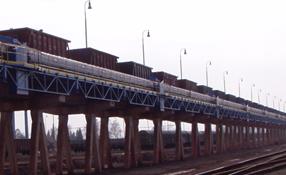

Fig. 2. Facility III: high ramp with tilter
|
|
|
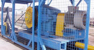
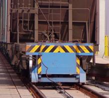
Fig. 3. Reel of pusher and carriage of
pusher
However, the rope was torn after
nearly a year of operations. Using another tension member, for example, chains
(cell or Gall’s), is not suitable because the rope represents the ideal
solution, given its elastic properties in relation to engagement.
Therefore, an analysis of the possible causes
of damage of the rope was carried out, which revealed that there was a
synergistic effect of several partial injuries.
|
|
|
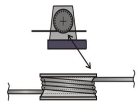
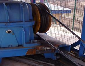
Fig. 4. Driving drum of a
continuous winch (SPIL)
The least reliable element, in terms
of an element that harms the rope the most, appears to be the driving drum
of a continuous winch (SPIL), through which the driving force is transmitted
from the engine to the rope. By multiple wrapping of the rope on the drum, in
order to ensure a sufficient angle of wrap and the resulting required driving
force, there is no ideal stacking of the rope on the drum (Figure 4, left). Due
to the influence of dynamic processes during the shifting of wagons, however, overlapping
of individual loops of rope occurs. This causes increased wear of the rope,
which, along with associated compression stress, leads to its rapid
degradation. Visual verification of this excessive wear highlights the amount
of “milled” tiny particles of rope wires around the drive drum (Figure 4,
right).

Fig. 5. The
principle of the proposed
change of rope drive
By examining the market
opportunities, rope sheave production approaches and design capabilities for
changing the existing equipment, the solution with the principle shown in Figure
5 is proposed. This solution was found to increase the angle of wrap to comply
with the required excess friction force, as well as remove the rope crossing
and increase the diameter of the drive drum to the maximum possible rate, i.e.,
from 600 mm to 800 mm. The given value of 800 mm is limiting for the preservation
of the existing drive; otherwise, it would be necessary to change the motor and
gearbox as well. Modifying the cable transfer is also proposed. Until now,
cable transmission 1 has been in use; for the proposed adjustment, we assume
one more sheave to be inserted, which will increase the cable transfer to i =
2, resulting in changes in the strength of the pull rope to a half value.
The recalculation of given
conditions, according to Equation (5), results in the following data: rope
diameter = 25 mm, diameter of the drive wheel D = 600 mm, cable transfer i = 1,
when considering that the maximum driving force S = 80 kN, which is the maximum pressure in the wrap pmax
= 16 MPa.
Given that the rotation capacity of
trans-shipment (for continuous operations) is 2.5 to 2.8 Mt/yr, the performance
of the tilter [2], including handling of BG wagons, which equates to 67 t/5 min.
It means that a tippler is able to serve 12 wagons per hour. According to Table
1, it should be from lifting machine group IV, where the number of cycles is up
to 30/hour and for which the recommended maximum pressure is about 10.2 MPa for
the travelling velocity, v = 0.328 ms-1. It can be seen that, for
the maximum pulling force, the permissible value is exceeded 1.57 times. A BG wagon
load is 67 t (for an NG wagon, it is 55 t). Wagons are drawn to the tilter one
by one, i.e., the maximum pressure in the wrap rope for the considered
coefficient of friction between the wheel and the rail wagon (i.e., 0.1) will
be pmax = 13.1 MPa. In other words, the value is again exceeded 1.28
times. In the proposed adjustment, when pulling one BG wagon into the tilter,
the maximum pressure pmax = 9.8 MPa would also create pressure
in the wrap drum with a diameter of 800 mm. If we were to use the rope
gear i = 2, then the maximum pressure would be pmax = 4.9 MPa,
which is less than half of the recommended maximum pressure value for the given
duty cycle.
4. CONCLUSION
This article has highlighted how the
specific load of steel wire rope, as well as the pressure between the rope
and sheave, pulley or drum, will enable the assessment of the durability or life
of such rope during a particular operation. At the same time, the example of
the pusher used with the tilter has shown that suitable design modification of
installed and routed cables can considerably extend the durability of this
transport-handling device.
This
paper was elaborated in the framework of the following projects: VEGA1/0197/14 –
research on new methods and innovative design solutions in order to increase
efficiency and to reduce emissions of transport vehicle driving units, together
with the evaluation of possible operational risks: VEGA 1/0198/15 – research on
innovative methods for emission reduction of driving units used in transport
vehicles and the optimization of active logistic elements in material flows, in
order to increase their technical level and reliability; and KEGA 021TUKE–4/2015 – development of
cognitive activities focused on innovations in educational programmes within
the discipline of engineering, as well as the building and modernization
of specialized laboratories, which are specified for logistics and
intra-operational transport.
References
1. Boroška
Ján, Hulín Jozef, Lesňák Oldřich. 1982. Oceľové
laná. [In Slovak: Steel ropes]. Bratislava:
Alfa. ISBN: 63-178-82.
2. Boroška
Ján. 2000. “Činitele ovplyvňujúce životnosť a bezpečnosť prevádzky oceľových
lán”. In International Conference “Výskum, výroba a použitie oceľových lán”:
15-21. KLaVS, Vysoké Tatry – Podbanské. [In Slovak: “Factors affecting the life
and safety of operation of steel ropes”. In International
Conference “Research, production and use of steel ropes”: 15-21].
3. Costello
George A. 1997. Theory of Wire Rope. New York:
Springer-Verlag.
ISBN: 0-387-98202-7.
4. Janovský
Lubomír. 1980. Výťahy a eskalátory.
[In Czech: Lifts and escalators]. Prague:
SNTL. ISBN: 04-228-80.
5. Molnár
Vieroslav, Gabriel Fedorko, Beáta Stehlíková, Peter Michalik. 2011.
“Statistical comparison of rope strands by ANOVA test and Kruskal-Wallis test”.
TEM Journal 11(6): 1121-1126. ISSN:
2217-8309.
6. Tokar
M., B. Arzenšek. 2002. “Failure of crane wire rope.” Engineering Failure Analysis 2(9): 227-233. ISSN: 13506307. DOI:
10.1016/S1350-6307(00)00047-9.
7. Costello
George A. 2003. “Mechanics of wire rope”. Wire
Journal International 36:
56-63.
8. Chaplin
C. R. 1995. “Failure mechanisms in wire ropes.” Engineering Failure Analysis 1(2): 45-57. ISSN: 13506307.
9. Stanova
E., G. Fedorko, M. Fabian, S. Kmet. 2011. “Computer modelling of wire strands
and ropes – part I: theory and computer implementation”. Advanced Engineering Software 42: 305-315.
10. Łazarz
B., G. Wojnar, H. Madej, P. Czech. 2009. „Evaluation of gear power losses from
experimental test data and analytical methods”. Mechanika 6(80): 56-63.
ISSN: 1392-1207.
Received 07.01.2015; accepted in revised form 22.04.2016
![]()
Scientific Journal of Silesian University of
Technology. Series Transport is licensed under a Creative Commons
Attribution 4.0 International License