Article citation information:
Kohl, O., Pesik, L. Evaluation of a driver�s seat�s dynamic properties. Scientific Journal of Silesian University of
Technology. Series Transport. 2016, 91,
59-69. ISSN: 0209-3324.
DOI: 10.20858/sjsutst.2016.91.6.
Ondrej KOHL[1],
Lubomir PESIK[2]
EVALUATION OF A DRIVER�S SEAT�S DYNAMIC
PROPERTIES
Summary. The springing support in a driver�s seat is a very serious issue, such
that manufacturers are increasing their efforts to optimize the dynamic
properties of this kind of seat. The main optimization criterion is vibration
insulation efficiency with regard to health research and associated health
standards and regulations. This article deals with the definition of the
optimal driver�s seat properties in relation to two examples of springing
systems with different kinds of damping. The first case involves the springing
support of a driver�s seat that uses a pneumatic spring and a telescopic
hydraulic damper. In the second case, the damping effect is achieved
by two pneumatic springs whose forces effect a phase shift due to a throttle
valve located in the connecting piping system.
Keywords: driver�s seat,
vibration minimization, oscillation, stiffness, damping
1. INTRODUCTION
The
springing support in a driver�s seat (Fig. 1) consists of a guide mechanism, in
which is placed a pneumatic spring. Parallel to the air spring is a guide
mechanism, which is connected to a damper (Fig. 2). Force effects ![]() �and
�and ![]() �are phase-shifted by
�are phase-shifted by ![]() .
.
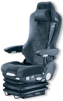
Fig. 1 Vehicle driver�s seat

Fig.
2. Springing seat support with a hydraulic damper
In
the original author�s solution, there are two air springs that, by themselves, create
force effects that act against each together. They are pneumatically connected
through the throttle valve, which achieves phase-shifting as a result of their
force effects ![]() �and
�and ![]() , and in turn a damping
oscillatory motion (Fig. 3).
, and in turn a damping
oscillatory motion (Fig. 3).
When
the vehicle is moving, the seat is kinetically energized by the movement of the
floor. The excitation function ![]() �is, in fact, in respect of frequency and
amplitude, very diverse, while its character depends on the road surface,
vehicle suspension and speed. Manufacturers of driver�s seats asses the dynamic
properties of the springing support and the vibration insulation effect
based on their own practices and policies. Typically, measurement and
evaluation of the feedback
�is, in fact, in respect of frequency and
amplitude, very diverse, while its character depends on the road surface,
vehicle suspension and speed. Manufacturers of driver�s seats asses the dynamic
properties of the springing support and the vibration insulation effect
based on their own practices and policies. Typically, measurement and
evaluation of the feedback ![]() �to the excitation signal
�to the excitation signal ![]() �take place when a vehicle is driving within a test
polygon. General evaluation, enabling an objective comparison of driver's seats
from different manufacturers, in terms of vibration insulation efficiency, is
practically non-existent.
�take place when a vehicle is driving within a test
polygon. General evaluation, enabling an objective comparison of driver's seats
from different manufacturers, in terms of vibration insulation efficiency, is
practically non-existent.

Fig.
3. Springing seat support with two air springs
2. MECHANICAL MODEL
The
basis for evaluating the driver's seat suspension system is undoubtedly the
creation and compilation of a mechanical model and solving equations of motion.
For
the commonly known system shown in Fig. 2, the equation of motion can be
written by simplifying assumptions of linearization dynamic parameters in the following
form:
![]() ,���������������� ����������������������������������� (1)
,���������������� ����������������������������������� (1)
where ![]() �is the reduced mass of the moving parts of the
seat including the driver,
�is the reduced mass of the moving parts of the
seat including the driver, ![]() �is the coefficient of vibration damper
damping,
�is the coefficient of vibration damper
damping, ![]() �is the spring stiffness,
�is the spring stiffness, ![]() �and
�and ![]() �are the springs and dampers transfers,
�are the springs and dampers transfers,![]() �is the displacement of the base under the
kinematic excitation, and
�is the displacement of the base under the
kinematic excitation, and ![]() �is the absolute displacement of the object.
�is the absolute displacement of the object.
It is then possible to rewrite Equation (1) as follows:
![]() ,������������������������������������������� ������� (2)
,������������������������������������������� ������� (2)
where ![]() �is the relative displacement of the object and
the base.
�is the relative displacement of the object and
the base.
For
pneumatic�mechanical systems, as shown in Fig. 3, it is possible to write the equation
of motion in the following form:
![]() ,���� ��������������������� (3)
,���� ��������������������� (3)
where ![]() �is the construction damping coefficient, while
�is the construction damping coefficient, while
![]() �and
�and ![]() �are transfers of springs in mechanism.
�are transfers of springs in mechanism.
The
springs of the resilient differential pneumatic support have their geometrical
characteristics given by polynomial functions of effective surfaces ![]() �and
�and ![]() , as well as volumes
, as well as volumes ![]() �and
�and ![]() . The forces in the
springs are also represented as follows:
. The forces in the
springs are also represented as follows:
![]() ������������������������������ �����������������(4)
������������������������������ �����������������(4)
and
![]() ������������������������������ ����������������(5)
������������������������������ ����������������(5)
�![]() �and
�and ![]() �represent deformations of the springs,
�represent deformations of the springs, ![]() �and
�and ![]() �represent air pressures in the springs, and
�represent air pressures in the springs, and ![]() �and
�and ![]() �represent effective surfaces of the springs.
The equation of motion in the support with the mass
�represent effective surfaces of the springs.
The equation of motion in the support with the mass ![]() �of the supported object is simple:
�of the supported object is simple:
![]() , ������ ���������������������������(6)
, ������ ���������������������������(6)
where ![]() �is the relative displacement of the object and
the base,
�is the relative displacement of the object and
the base, ![]() �is the displacement of the base under the
kinematic excitation,
�is the displacement of the base under the
kinematic excitation, ![]() �is the absolute displacement of the object,
�is the absolute displacement of the object, ![]() �is the construction damping of the mechanism,
and
�is the construction damping of the mechanism,
and ![]() �is the static load of the mechanism. The
function
�is the static load of the mechanism. The
function ![]() �is the equivalent force from the springs:
�is the equivalent force from the springs:
![]() ,
������������ �������������������������������(7)
,
������������ �������������������������������(7)
where ![]() �and
�and ![]() �are transmission ratios of the springs.
�are transmission ratios of the springs.
Air pressures inside the springs obey the state equation of ideal gas:
![]() ,���������������������������������������������������� ����������� (8)
,���������������������������������������������������� ����������� (8)
and
![]() ���������������������������������������������������� ������������(9)
���������������������������������������������������� ������������(9)
where ![]() �and
�and ![]() �are masses of the air enclosed inside the
springs,
�are masses of the air enclosed inside the
springs, ![]() �is the specific gas constant, and
�is the specific gas constant, and ![]() �and
�and ![]() �are temperatures of the air inside the
springs.
�are temperatures of the air inside the
springs.
The air exchange
between the springs is described by isentropic airflow through the throttle
valve. In the next two equations, the rate of air exchange depends on pressures
![]() �and
�and ![]() ; the pressure
; the pressure ![]() �denotes the higher pressure of
�denotes the higher pressure of ![]() �and
�and ![]() �at a given time, while
�at a given time, while ![]() �represents the remaining one. The sign of the
flow rate is determined by the two pressures that are higher. The rate of air
mass is then calculated thus:
�represents the remaining one. The sign of the
flow rate is determined by the two pressures that are higher. The rate of air
mass is then calculated thus:
 ��������������������������������������������(10)
for
subcritical flow conditions where ![]() ; otherwise,
; otherwise,
 .���������������� ��������������������������������� �(11)
Critical pressure ratio ![]() is determined thus:
is determined thus:
![]() ������������������������������������������������� �������������������(12)
������������������������������������������������� �������������������(12)
where ![]() �is specific heat ratio for the air. In Equations
(9) and (10),
�is specific heat ratio for the air. In Equations
(9) and (10), ![]() �is the discharge coefficient and
�is the discharge coefficient and ![]() �is the cross-section of the throttle valve.
�is the cross-section of the throttle valve.
The
differential Equation (8), which is supplemented by a differential equation for
air mass inside the springs, describes the pneumatic-mechanical system
being presented in this article. As we have considered a closed pneumatic
system, the air masses are bound by the following condition:
![]() ������������������������������������������� ���������������(13)
������������������������������������������� ���������������(13)
Given that
thermal effects are within the scope of this article, temperatures ![]() �and
�and ![]() �are considered as state variables. The evolution
of the air temperatures in time is described by the following differential
equations, which are derived from internal energy conservation (first law of
thermodynamics):
�are considered as state variables. The evolution
of the air temperatures in time is described by the following differential
equations, which are derived from internal energy conservation (first law of
thermodynamics):
![]() ������� ��(14)
������� ��(14)
![]() ����������(15)
����������(15)
where ![]() �is the isochoric thermal capacity of the air,
�is the isochoric thermal capacity of the air, ![]() �is the ambient temperature, and
�is the ambient temperature, and ![]() �is the coefficient of heat transfer. For
the purpose of this article, the heat transfer coefficient is presumed to
involve both the conductive and convective heat transfer.
�is the coefficient of heat transfer. For
the purpose of this article, the heat transfer coefficient is presumed to
involve both the conductive and convective heat transfer.
3. EVALUATION OF SPRINGING SUPPORT
Based
on the solutions of equations of motion in the preceding section, a
transmission frequency characteristics can be obtained, which are usually
concerned with the displacement amplitude of the oscillatory movement of the
seat. According to these data, the function of the spring base, due to
changes in the position of the driver in relation to the vehicle controls, can
be evaluated, thereby allowing the appropriate size of the damping coefficient
to be set.
Regarding
the springing support with a hydraulic damper, as shown in Fig. 2, the
transmission frequency characteristics are based on those presented in Fig. 4.
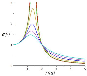
Fig. 4. Transmission
frequency characteristics of springing support with a linear hydraulic damper
Particular
damping characteristics correspond to the relative damping coefficient of 0.01,
and 0.1 to 0.5 with step 0.1. Generally, it is possible to say that damping has
a positive effect when the system is erected near to its natural frequency.
Outside of this region, the damping importance, with respect to the
displacement amplitude, is either small or rather negative.
Regarding
the springing support, as shown in Fig. 3, the transmission frequency
characteristics are based those presented in Fig. 5.
Individual
characteristics correspond to different intensities throttling the flow of
compressed air between the two air springs in the support. The diameters of the
holes are graded from 1 mm to 3.5 mm in steps of 0.5 mm. The damping character
of the oscillation in this case is favourable in the wider frequency range and
the gain does not exceed the value of 1.5.
Fig. 5. Transmission frequency
characteristics of springing support with two air springs
Another evaluation
criterion relating to vibration insulation for a driver�s seat concerns
acceleration value and frequency, which act on the driver and adversely affect
driving comfort.
Fig. 6 presents acceleration
transmission frequency characteristics of springing support with a linear
hydraulic damper. It shows that damping decreases displacement amplitude, but
significantly increases the acceleration values. This fact means that vibration
insulation system seats, located outside the resonance region, require
negligible damping.
Fig. 6. Acceleration amplitude
frequency characteristics of springing support with a linear hydraulic damper
Fig.
7 presents the acceleration amplitude frequency characteristics of springing
support with two air springs.
This
springing system significantly reduces amplitude acceleration values compared
to the classic springing support design. Acceleration amplitudes increase
almost linearly with excitation frequency.
Fig. 7. Acceleration amplitude
frequency characteristics of springing support with two air springs
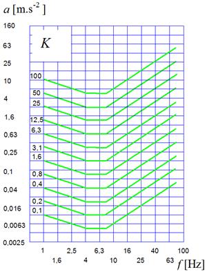
Fig. 8. Amplitude and frequency dependence in
relation to the comfort of the seated human on acceleration
Vibration isolation properties of
the driver�s seat can be quantified on the basis of hygiene standards. Medical
research has indicated that the result is defined by the sitting person's
comfort under the influence of acceleration with a certain amplitude and
frequency. Fig. 8 presents graphs taken from the internationally valid
standards ISO 2631, ISO 5982 and VDI 2057.
Using these findings
could contribute to an objective evaluation of vibration insulation properties
of driver�s seats, as well as remove the element of subjective assessment,
which currently dominates among the manufacturers of driver�s seats.
Using the coefficient
![]() , the vibration insulation level of
the driver�s seat properties can be deduced. In Fig. 9, dependence on the
coefficient
, the vibration insulation level of
the driver�s seat properties can be deduced. In Fig. 9, dependence on the
coefficient ![]() �is calculated according to the seat�s
excitation frequency with a hydraulic telescopic shock absorber, while Fig. 10 presents
this dependence on the seat involving two pneumatic springs.
�is calculated according to the seat�s
excitation frequency with a hydraulic telescopic shock absorber, while Fig. 10 presents
this dependence on the seat involving two pneumatic springs.
Fig. 9. Frequency dependence the
coefficient of seated human loading on the acceleration of a seat with a hydraulic
telescopic shock absorber
Fig. 10. Frequency dependence the
coefficient of a sitting human loading on the acceleration of a seat with two
air springs
4. CONCLUSION
There
are many technical problems that are connected with the need to minimize
vibrations, especially in the automotive industry. There are many types of
equipment that produce an excitation through the movement of the foundation. A typical
example in this respect a driver�s seat. Although vibration isolation is
possible for these objects, there are further problems that come from a variable
excitation frequency. It is clear that the condition in terms of the sufficient
difference between the force excitation frequency and resonant frequency of the
dynamic systems cannot be ensured at all times. In these cases, it is necessary
to use special supports with the possibility of changing the stiffness, as well
as tune the natural frequency of the system appropriately. In this article, two
possible designs for a driver�s seat were presented. One of them is the
classical solution with a hydraulic damper. The second one is an original
solution by the authors, involving two pneumatic springs in the guide
mechanism.
This
original solution comes in the form of a pneumatic spring system with a
differential configuration and throttling of the airflow between the springs.
The springs act against each other. This system can be used in order to produce
benefits to the vibration isolation of objects by using kinematic excitation,
e.g., driver�s seats, ambulance couchettes etc. Based on the frequency
spectrum of excitation, it is possible to choose the optimum cross-section of
the throttling element, along with achieving efficient damping of vibrations in
a relatively broad range of low excitation frequencies. Similar results can be
seen in the measurements obtained in a real system.
Evaluation
of both seats is made on the basis of simulating vibration excitation at
constant amplitude support displacements at frequencies between 0 and 5 Hz. The
obtained frequency characteristics of kinematic quantities are further
processed in terms of vertical acceleration coefficient determination regarding
the seated human loading.
Calculation
results showed that a qualitatively higher level of vibration insulation
properties was found in the seat with two air springs.
References
1.
D. J. Whitehouse.
2011. Handbook of surface and
nanometrology. Boca Raton: CRC Press.
2.
Zeman V., Z.
Hlav��. 2010. Kmit�n� mechanick�ch
soustav. [In Czech: Mechanical
vibration]. Plze�: Z�pado�esk� univerzita v Plzni.
3.
Pe��k L., A.
Skarolek. 2012. �Heat transfer effects on vibration isolation differential
pneumatic system�. Transactions of the
Universities of Ko�ice: 109-114. Ko�ice: Research reports from the
Universities of Ko�ice. ISSN 1335-2334.
4.
Pe��k L., A.
Skarolek. 2011. �Tuning of vibration isolation differential pneumatic system
by means of throttle valve�. Transactions
of the Universities of Ko�ice: 191-196. Ko�ice: Research reports from the
Universities of Ko�ice. ISSN 1335-2334.
5.
Dresig
H., F. Holzwei�ig. 2008 Maschinendynamik.
[In German: Machine
dynamics] Berlin: Springer Verlag.
6.
Harris
C. M. 2005. Shock and Vibration Handbook.
New York: McGraw-Hill.
7.
Homi�in
J., P. Ka��ay. 2014. �Experimental verification of the possibility using
pneumatic flexible shaft couplings for the extremal control of torsional
oscillating mechanical system�. Diagnostyka
15(1): 11-16. ISSN 1641-6414.
8.
PL
216901 B1. Uk�ad mechaniczny
strojony w spos�b p�ynny. [In Polish: Mechanical
system tuned smoothly]. Homi�in Jaroslav. 2014. Warsaw: Polish Patent
Office.
9.
Grega
R., J. Kraj��k. 2012. �The
pneumatic dual-mass flywheel�. Scientific Journal of Silesian University of
Technology. Series Transport 76: 19-24. ISSN: 0209-3324.
10. Urbansk� M., J. Homi�in. 2015. �Design of a mobile platform for a mobile
torsional oscillating mechanical system�.
In�ynier 21. Wieku: 389-394. ISBN: 978-83-65182-29-6.
11.
Ku�ka
J., M. Manti�. 2014 �Effect of operational
condition changes on the durability of the rope for pusher of circular wagon tipper�.
Applied Mechanics and Materials 683:
28-32. ISSN 1660-9336.
12.
Grega
R. et al. 2015 �The chances for reduction of vibrations in mechanical system
with low-emission ships combustion engines.� International Journal of Maritime
Engineering 157 (A4): 235-240. ISSN 1479-8751.
13.
Medveck�-Be�ov�
S., J. Kraj��k. 2015. �Modifications to a gearbox that increase the performance
of a winding machine for steel sheets�. IT-stroj�r: 1-3.
ISSN 1338-0761.
14.
Medveck�-Be�ov�
S., J. Vojtkov�. 2014. �Application
of asymmetric profile in gearing in gearings with eccentric gears�. Scientific Journal of Silesian University of
Technology. Series Transport 85: 89-93. ISSN: 0209-3324.
15.
Homi�in
J., M. Urbansk�. 2015. �Partial
results of extremal control of mobile mechanical system�. Diagnostyka 16(1): 35-39. ISSN 1641-6414.
16.
Homi�in
J., P. Ka��ay, M. Urbansk�. 2011. �High-flexibility characteristics of
pneumatic flexible shaft couplings.� Pneumatyka 79(2): 26-29. ISSN 1426-6644.
17.
Manti� M., J. Ku�ka, J. Kraj��k, M. Kopas, M. Schneider. 2015. �Influence of selected digitization methods on final
accuracy of 3D model�. Production Management and Engineering Sciences: 475-480. Proceedings of the International Conference
on Engineering Science and Production Management (ESPM 2015). Tatransk�
�trba, High Tatras Mountains, Slovak Republic, 16-17 April 2015. Edited by
Majern�k M., D. Naqib, B. Martin. Boca Raton: CRC
Press (Taylor & Francis Group). ISBN: 978-1-138-02856-2.
18.
Medveck�-Be�ov�
S., M. Manti�, R. Grega. 2014. �The
stress analysis in dangerous section of gear teeth�. Applied Mechanics and Materials 611: 279-283.
ISBN 978-3-03835-189-4. ISSN 1660-9336.
19.
Vojtkov�
J., 2011. �Force proportions
of the worm in planetary toroidal roller gear�.
Transactions of the Universities of
Ko�ice 2: 77-82. ISSN 1335-2334.
20.
Kopas
M., E. Faltinov�. 2012. �Optimisation
aspects in design process of specific structural element in bulk solid storage bin�.
Transactions of the Universities of
Ko�ice 3: 19-24. ISSN 1335-2334.
21.
Grega
R., J. Kraj��k. 2013. �The
application of pneumatic flexible coupling in conveyor drive�. Technol�g 5(4): 51-54. ISSN 1337-8996.
22.
Grega
R., J. Homi�in, P. Ka��ay, J. Kraj��k. 2011. �The analysis of vibrations after changing shaft coupling
in drive belt conveyer�. Scientific
Journal of Silesian University of Technology. Series Transport 72: 23-31.
ISSN: 0209-3324.
Received 03.01.2016; accepted in revised form 11.05.2016
![]()
Scientific Journal of Silesian University of
Technology. Series Transport is licensed under a Creative Commons
Attribution 4.0 International License