Article citation info:
Urbanský, M., Kaššay, P. The new realized mobile device for extremal
control research and presentation. Scientific
Journal of
Matej URBANSKÝ[1],
Peter KAŠŠAY[2]
The
new realized
Summary. At our
department we deal with torsional oscillating mechanical systems (TOMS)
continuous tuning during its operation in terms of torsional oscillation size. Therefore
was build the new mobile device for research and presentation purposes of the
TOMS continuous tuning using extremal control method. This paper deals mainly with
design of the mobile device and its special compressed air distribution system,
which is necessary for its regular function.
Keywords: torsional
oscillating mechanical system, continuous tuning, extremal control
1. INTRODUCTION
In
the laboratory of our workplace – Section of machine design and machine parts
of Department of Construction, Automotive and Transport Engineering we attend
to measuring and tuning of torsional oscillation in torsional oscillating
mechanical systems (TOMS), mainly during their operation, i.e. publications [1-6, 8].
One of the methods of continuous tuning is the application of the extremal control
– experimental optimization, which is detailed described i.e. in publications
[2-4]. For research and presentation purposes of TOMS continuous tuning using
extremal control method was build the new mobile mechanical device (Fig. 1).
For regular function of this device was moreover necessary to build the special
compressed air distribution system. This paper therefore deals with design of
this mobile device and its special compressed air distribution system and with determination
of volume of air springs, which are modified and used as air pressure tanks.
2. DESCRIPTION OF THE NEW BUILD
In Fig. 1 we can see that the basic
part of this new build mobile device is the torsional oscillating mechanical
system (TOMS). This TOMS consists of 3-phase asynchronous electromotor MEZ
4AP132M-4 (nominal power 7,5 kW at 1450 min-1) (1), whose
rotation speed is continuously vector-controlled by the frequency converter
Sinamics G120C (2). Electromotor drives the 3-cylinder piston compressor ORLIK
3JSK-75 (3) through the pneumatic tuner of type 4-2/70-T-C (4). This TOMS
is situated on rigid frame, which is flexibly mounted on the mobile platform
(5). Next component situated on the mobile platform (5) is electronic extremal
control system called ESLER (6) and its accessories (sensors, actuators, etc.).
Current level of ESLER function is in detail described in [4] and the whole
process of torsional oscillation data measuring and evaluation using optical
sensors is described in detail in [8].
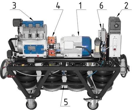
Fig. 1. The new build mobile device
for extremal control presentation
As base for the mobile device
construction was therefore used the standard ORLIK compressor system
(Fig. 2), with originally air pressure tank (
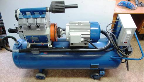
Fig. 2. The standard compressor
system ORLIK
3. MOBILE PLATFORM WITH compressed air distribution system
The main parts of the mobile platform
(position (5) in Fig. 1) are the steel frame, four air springs RUBENA
340/3, modified (Fig. 3) and used as air pressure tanks and the special
compressed air distribution system (Fig. 4).
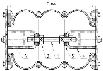
Fig. 3. The modified air spring
The mobile platform must insure the
following functions:
■ carrying and transport of whole system,
■ compressed air storage for pneumatic coupling inflation,
■ compressor delivery pipe volume compensator
for properly adjustment of compressor delivery pressure and thereby TOMS load
too.
Modified air springs RUBENA 340/3
were used as air pressure tanks (Fig. 3). The threaded rod (1),
situated in air spring axis (axis of rotational symmetry) with four lock-nuts
(2) screwed on it are keeping from unwanted air spring extension at its
inflation and unwanted air spring retraction at its deflation, mainly when in
the air spring is zero overpressure value. Axial forces from air spring sealing
flanges (3) to the threaded rod are transmitted through cross-stiffened forks
(4), welded to inner sides of air spring sealing flanges. The hard rubber
plates (5) between lock-nuts allow small parallelism deviations of air spring
sealing flanges. The air spring stroke is therefore constant and it is adjusted
to value Hmax = 340 mm, which is maximal air spring
stroke operation value according to manufacturer catalog [8]. Maximal air
overpressure in the tanks is 700 kPa.
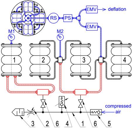
Fig. 4. The special
compressed air distribution system
The special compressed air
distribution system (Fig. 4) allows through inter-connections the use of
modified air springs as:
■ compressed air storage for pneumatic coupling inflation (air
springs 2,3,4),
■ compressor delivery pipe volume compensator (air spring 1).
In Fig. 4 we can see that the
compressed air from compressor streams into the compressor delivery pipe (1)
(1" piping), which finished with throttle valve (2) and noise
silencer (3). With this throttle valve we can adjust compressor delivery
overpressure and thereby the TOMS load too, since the transmitted load
torque in TOMS at certain constant rotational speed increases with increasing
compressor output air overpressure [9]. For accurate and comfortable adjustment
of compressor delivery pressure is to delivery pipe connected the volume
compensator (air spring 1). Whole compressor delivery pipe is protected against
inadmissible overpressure increase by mechanical safety pressure valve (4)
(after backflow valve (5)) and by electrical safety pressure valve – total
stopper (before backflow valve, do not shown in Fig. 4). Interconnected
air springs 2,3,4 serve as compressed air storage for pneumatic coupling
inflation. Compressed air streams through electromagnetic valve (EMV), pressure
sensor (PS) and rotational air supply (RS) into pneumatic coupling. Air spring
1 and interconnected air springs 2,3,4 can be using ball lock valves (6)
alternately connected on or disconnected off the compressor delivery pipe, as
necessary. It is necessary to say that all actuating components (2), (6) and
indicators (manometers M1 and M2) must be situated so close together as
possible and they must allowing good manipulation and view. At the same time
that components must be situated beyond reach of rotary or electrical parts of
mechanical system. In our case they are situated on the left frame forehead
(Fig. 1).
4. APPROXIMATE determination of air springs volume
For computation of certain next
parameters of the system was necessary to determine the approximate volume
of modified air springs, described in previous chapter. This determination was
realized on the principle of air pressure equalization between known volume VN
(
 (1)
(1)
Where ppN is air
overpressure in the
Because of isothermal process was
considered, it was important to wait enough long time for ppC and ppN
values consolidation. For accurate measurement of the pressure was used the pressure
sensor of type Danfoss MBS 3000 (0÷10 bar range of measure).
Table 1
Measured and computed values for air springs volume determination
|
ppN [kPa] |
800 |
750 |
700 |
650 |
600 |
550 |
500 |
450 |
400 |
|
ppC [kPa] |
628,6 |
590,3 |
552 |
513,5 |
474,6 |
435,8 |
397,1 |
358,4 |
319,5 |
|
volume VS [l] |
81,7 |
81,2 |
80,4 |
79,7 |
79,3 |
78,6 |
77,7 |
76,7 |
75,6 |
|
1 air spring volume [l] |
20,17 |
20,04 |
19,86 |
19,69 |
19,57 |
19,40 |
19,18 |
18,92 |
18,65 |
From Tab. 1
we can see that the average 1 air spring volume is 19,5 l. Values of VS
increase with increasing ppN values. This fact is caused by extensibility
of air springs rubber-textile coat. Volume of 1 air spring is computed without
the piping-volume.
5. CONCLUSION
In term of safety of our new build
mobile device is even necessary to install protection covers in TOMS, namely:
■ rotary parts cover, mainly over pneumatic coupling,
■ pneumatic system cover around steel frame,
■ electrical parts cover over choke coil and frequency converter
terminal board.
References
1.
Grega
Robert. 2014. „Examination of
applicated pneumatic flexible coupling and its effect on magnitude of vibrations
in drive of belt conveyer”. Scientific
Journal of Silesian University of Technology. Series Trasnsport 85 (4):
21-25. ISSN 0209-3324.
2.
Homišin
Jaroslav. 2002. Nové typy pružných
hriadeľových spojok: Vývoj-Výskum-Aplikácia. Košice: Vienala. ISBN
80-7099-834-2. [In Slovak: New types of
couplings flexible shaft: Development-Research-Application].
3.
Homišin
Jaroslav, Peter Kaššay. 2014. „Experimental
verification of the possibility using pneumatic flexible shaft couplings for
the extremal control of torsional oscillating mechanical system”. Diagnostyka 15 (2): 7-12. ISSN
1641-6414.
4.
Homišin
Jaroslav, Matej Urbanský. 2015. „Partial
results of extremal control of mobile mechanical system”. Diagnostyka 16 (1): 35-39. ISSN 1641-6414.
5.
Patent
no.259225. Regulačný systém pre
zabezpečenie plynulej zmeny charakteristiky pneumatických spojok. Homišin
Jaroslav. 1987. [In Slovak: Regulatory
system to ensure smooth changes in the characteristics of pneumatic clutches].
6.
Patent PL 216901 B1. Układ mechaniczny strojony w sposób płynny. Homišin J. 2014. [In Polish: Mechanical tuned smoothly].
7.
Rubena. „Air Springs / Couplings / Compensators /
Washers”. Available at:
http://www.rubena.cz/air-springs/t-659/
8.
Urbanský
Matej, Jaroslav Homišin. 2014. „Use
of optical sensors for measuring of torsional oscillation size”. In:
Inżynier 21. wieku: 4. Międzynarodowa
Konferencja Studentów oraz Młodych Naukowców: 343-348. Akademia
Techniczno-Humanistyczna, Bielsko-Biała, Poland. 05 December 2014,
9.
Urbanský
Matej, Pavol
This paper was written in the
framework of Grant Project VEGA: „1/0688/12
– Research and application of universal
regulation system in order to master the source of mechanical systems
excitation”.
Received
23.10.2014; accepted in revised form 25.06.2015
![]()
Scientific Journal of