Article citation info:
Medvecká-Beňová, S. Deformation and stiffness of spur gear teeth and their influence on gear noise. Scientific Journal of Silesian University of Technology. Series Transport. 2015, 89,

101-107. ISSN: 0209-3324. DOI: 10.20858/sjsutst.2015.89.11.
Silvia MEDVECKÁ-BEŇOVÁ[1]
DEFORMATION AND STIFFNESS OF SPUR GEAR TEETH AND THEIR INFLUENCE ON GEAR NOISE
Summary. Gear teeth are deformed due to the load. The
deformation of gear teeth is causing some negative as well as positive effects.
A tooth has a complex shape and due to the complex shape of the teeth, a
theoretical determination of the deformation is difficult. The existing
experimental techniques are based on static deflection measurements gearing
loaded of constant force or seismic measurement deviations at slow rotation.
Recently, at ever faster evolving computer technology and the available
literature, we can encounter modern numerical methods, such as finite element
method (FEM), which can serve as methods for the determination of teeth of gearing. The article is devoted to the problems
of gearing stiffness analysis. The problem is solved for spur gears.
Deformation analysis solved by FEM is used for calculations of the gearing
stiffness. There are many influences that cause vibrations in the gearbox and
that have to be taken into account already in the phase of design, manufacture,
installation and operation. Detailed
analysis of gearboxes manufacturers have shown that improving of the gear
accuracy cannot reduce the transmission unit noise to the desired level. Only
fundamental changes to the shape of the tooth and changes in production
technology can achieve stronger noise reduction of gear mechanism.
Keywords: spur gear, gear noise, teeth deformation,
stiffness, FEM
1. Introduction
The
development of engine plants in past focused on the aquisition of the highest
capacity and durability. Engines and machines with gear transmission are very
popular and draw sufficient attention. Lowering the weight of the construction
machines and engine plants as well as increasing their efficiency and
productivity, are all part of the compelling task the construction, technology
and research workers must accomplish. These intensity factors have often a
significant influence on the increment of vibrations and noise in the monitored
engine plants. The society becomes gradually more intetested in these noise and
vibration emissions produced by the gearing mechanisms. The issue of lowering
noise emission in a gearbox is interconnected with the sources of noise,
together with measurement and evaluation of vibrodiagnostic performance.
Current products constructed with the usage of computer programs for the
firmness check of suggested solutions (FEM) together with the rich experience
of construction workers, reach optimal parameters from the perspective of
rigidity, material utilization and longetivity.
2. SOURCES OF
NOISE IN THE GEARBOX
The
gearbox is an audible enclosed system, from which the noise travels through
vibrations of the closet surface or plugged aggregates inclusive of the base
construction. One of the essential causes of noise is so-called transmission
error. This error is related to kinematic accuracy and durability of the
cogging.
The
vibrations from the spur gear, transmitted to the case of gearbox, are the most
important source of noise. From the physical point of view, the cause of
vibrations is the dynamic force which can change its amplitude, direction
or origin. The most critical change of amplitude in the evolvent cogging, which
main cause is stiffness of teeth and bursts when cogs enter the gear, due to
the deformation, deviation of gaps and cog profile from the theoretical ones.
Many other effects, i.e. vibrations transmitted into the cogging from the driving
or powered aggregate, oscillation of the arbors and bearings, influence the
vibrations in cogged wheels in a mesh. All of these elements play a role in the
enlargement of amplitude in cogging. The total energy of the radiated noise
further increases.
A dominant contribution of noise in
a gearbox; however, comes from the creation of vibrations during
intervention of the cogged wheels. On Figure 1, a total evaluation of
gearbox noise in an automobile, where the contribution of separated noise of
the gearbox intervention (defined as N and 3) is at maximum 40 % of the gearbox
noise with acontribution of 53% to the total noise, is displayed. The remaining
47% constitute for the background noise (defined as Bgr), inside which mainly
the noise created by bearing is incorporated [6].
The
noise in gear transmissions particularly affects periodic change of stiffness
teeth during meshing caused by changing the number of pairs of teeth, which are
simultaneously in meshing.
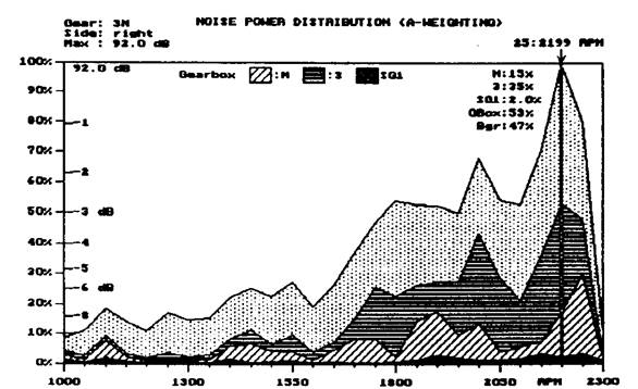
Fig. 1. Example
of evaluation of noise
gearbox of car [6]
3.
THE TEETH STIFFNESS AND THEIR IMPACT FOR
GEARBOX NOISE
Periodic
changes in the stiffness tooth mesh, caused by changes in the number of pairs
of teeth, which are also mesh in a significant noise impact on teeth. Stiffness
of gearing is defining as a proportion load across the width of the teeth and
the resulting deformation [1]. Since the involute tooth of spur gear has a
complex shape, the theoretical determination of the deformation the tooth
is a difficult. The
existing experimental techniques are based on static deflection measurements
gearing loaded of constant force or seismic measurement deviations at slow
rotation. Recently we can meet with modern numerical methods, such as finite
element method (FEM), which can serve as one of the methods for the determination
of deformation gearing [4]. As the basis for calculating the stiffness of
gearing results serve deformation analysis examined gearing solved by FEM.
Create
a geometric model of the gear is considered the first step to deal with tooth
deformation FEM. Universal user to create geometry computer model does not
exist. In this case, the geometric model has been created a combined method.
The final shape of 2D was by created in program AutoCAD. 3D model of examined
the spur gear with straight teeth was by created in program COSMOS/M as editing
from the 2D model. To determine the computer model for studying deformation of
the teeth using FEM was necessary to determine the material constants,
define the type of finite element, and selecting appropriate boundary
conditions (geometry and power).
We
will focus on the value of the total deformation in the direction of action
forces. To determine the deformation of gearing under load is necessary to
know the apportionment of the load on each gearing pairs with two pairs
meshing. At the beginning was considered with the simplest, ideal load
apportionment. The load for the two pairs meshing is divided by half for each
couple of teeth in the meshing.
To
determine the resulting deformation of the teeth is necessary to determine the deformation
of individual pairs. In Figure 2 shows the progress of the overall deformation
of teeth solved by FEM for the spur gears with number of teeth z1,2=24, the module of teeth m=3,75[mm], the force FN=1000[N] and width of gearing
b1,2=10[mm], which in the
meshing reaching gear ratio 1 and for the ideal division of load. Deformation
of pairs of teeth over the meshing along the length of meshing line is changes.
Maximum value
of deformation shall in this case the endpoints lonely meshing (if we consider
the image-pair) and the minimum value shall also meshing in two pairs of
endpoints lonely meshing. The points B and D, it is the solitary meshing
points leads to a step change deformation teeth and it will input the next
couple teeth to meshing.
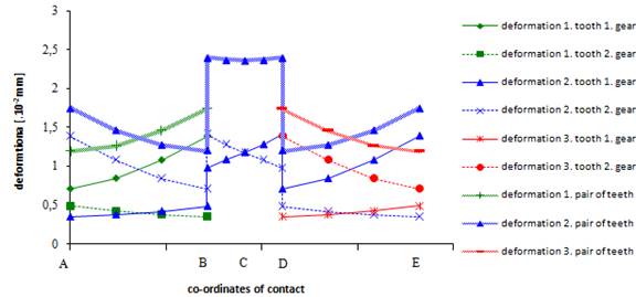
Fig.
2. Course
of tooth deformation
One
of the ways to specify the tooth stiffness is calculated using the total
deformation gearing determined by finite element method (FEM). In general the resulting stiffness c defined
by equation (1):
![]() , p = I, II
[N/mm.μm] (1)
, p = I, II
[N/mm.μm] (1)
where:
w
− load across the width of the teeth, equation (2) [N/mm] ;
δ
− the resulting deformation [μm].
![]() (2)
(2)
where:
wI − load across the
width of the first pair of teeth [N/mm] ;
wII − load across the width of the second pair of teeth [N/mm].
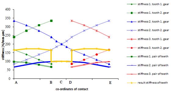
Fig.
3. Course
of tooth stiffness
In Figure 3 shows the course of total stiffness of the teeth, tooth pair
stiffness and total stiffness of gear teeth for the spur gears, in the teeth,
which in the meshing reaching gear ratio 1. The stiffness is individual pairs of teeth in the
mesh by changing the length of the engaging line. The minimum value shall end
in the engaging points
and lines shall
at maximum point
lone mesh, the so-called pitch point C. The resulting stiffness teeth after
track mesh changes periodically with
a period equal to the basic
pitch frontal. The endpoints solitary
mesh leads to sudden changes in stiffness resulting teeth. This
is due to a step change in deformation resulting
from the entry into another
pair of teeth in the mesh his cause’s vibrations that
cause noise gearbox.
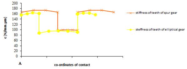
Fig.
4. Comparison
of stiffness
In figure 4 shoes the comparison of stiffness of spur gear and elliptical
gear. The elliptical gear is gear with variable transmission in the range
u = 0,5 to 2,0 ,with the number of teeth z1 = z2 = 24 and gearing module
mn= 3,75[mm] the distance a = 90[mm] and for a one direction of rotation. They are elliptical gears with axes of
rotation of gears placed eccentrically (Figure 5). The centers of rotation are
also focus points of the ellipse. Curved
active surface of tooth forms is involuta. Torque transmission ensures shape
bonded between meshing gears. The gearing consists of two identical gears. In Figure 4 shows the progress of the overall stiffness of teeth,
which in the meshing reaching gear ratio 1. Applies to, that if is the curve of the stiffness smooth, the noise in
gearing is lower. Then the noise
in elliptical gear is higher than the noise in the spur gear during meshing.
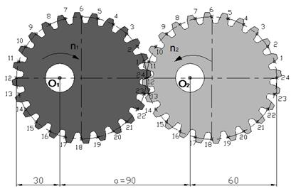
Fig.
5. Designed elliptical gear
4. CONCLUSION
There are many influences that cause vibrations in
the gearbox to be taken into
account already in
the design, manufacture, installation
and operation. Detailed analysis of gearboxes manufacturers have shown that improving the accuracy of gears cannot
reduce noise transmission
unit to the desired level. Only fundamental changes to the shape of the tooth and
changes in production technology can
achieve stronger noise
reduction gear mechanism.
This paper
was written in the framework of Grant Project VEGA: “1/0688/12– Research and
application of universal regulation system in order to master the
source of mechanical systems excitation.”
References
1.
Czech P., P. Folęga,
G. Wojnar. 2009. „Evaluation of influence of
cracking gear-tooth on hanges its stiffness“. Acta Technica Corviniensis – Bulletien of Engineering 4: 17- 22.
2.
Hyben B., M. Žmindák, A. Sapietová. 2013. “Dynamic
analysis of the properties of point machine EP600”.Technológ 04: 67-70. ISSN 1337-8996.
3.
Jakubovičová L. 2013. “Analysis of the roller bearing
mutual slewing effect on limit contact stress values”. Technológ 04: 79-82. ISSN 1337-8996.
4.
Medvecká-Beňová S. 2007. „Analysis of factors which are
influence of noisiness of change gearbox“. Acta
Mechanica Slovaca 11(4-A): 43-48. ISSN 1335-2393.
5. Medvecká-Beňová
S. 2011. „Deformácia a tuhosť čelného
ozubenia“. Strojárstvo 15(12):
8-9. ISSN 1335-2938. [In Slovak: “Deformation and stiffness spur”].
6.
Medvecká-Beňová S., Bigoš P. 2013. „Analysis of noise reduction of gear
transmissions“. In 13th
International Multidisciplinary
Scientific Geoconference: Ecology, Economics, Education and Legislation: 16-22. June,
2013, Albena, Bulgaria. ISBN 978-619-7105-04-9. ISSN 1314-2704.
7.
Satiepkova A., V. Dekys, M. Budinsky. 2012. “Utilizing
of sensitivity analysis in preparation of optimizing procedure”. Scientific Journal of Silesian University of
Technology. Series Transport 76: 113-118. ISSN 0209-3324.
Received 11.05.2015; accepted in revised form 21.09.2015
![]()
Scientific Journal of Silesian University of
Technology. Series Transport is licensed under a Creative Commons Attribution
4.0 International License