Article
citation information:
Galik, J., Kohar, R., Brumercik, F., Hudec, J.,
Patin, B. Increasing
the safety of a device using the TRIZ methodology. Scientific Journal of Silesian University of Technology. Series
Transport. 2021, 111, 43-56.
ISSN: 0209-3324. DOI: https://doi.org/10.20858/sjsutst.2021.111.4.
Jan GALIK[1],
Robert KOHAR[2],
Frantisek BRUMERCIK[3],
Juraj HUDEC[4],
Branislav PATIN[5]
INCREASING THE
SAFETY OF A DEVICE USING
THE TRIZ METHODOLOGY
Summary. The safety of
machinery is a very important aspect for its correct functioning in the
conditions of modern production or assembly. According to the standards,
manufacturers of special-purpose machines and devices are obliged to provide
their equipment with a certificate of conformity (CE). This article describes
the concerns of insufficient safety of a device. Insufficient coverage of part
of the line meant that the certification did not take place, and the safety
requirements were not met. The TRIZ method was used to resolve this technical
discrepancy, providing designers with "instructions" on how to
proceed, solve complex problems at the level of discrepancies and create
solutions. By agreement of the designers, a solution that was not economically
and implementation-intensive was created. All doors and windows within the
fencing have been reinforced, thus achieving a greater degree of security.
The resulting solution was subjected to simulations in the Ansys Workbench
program, and the FEM analysis led to certain conclusions. The results were then
moved to the structural engineer to assess the solution, who then approved the
solution and successful certification of part of the device, respectively, in
the assembly line.
Keywords: special-purpose
machines, safety, TRIZ
1. INTRODUCTION
Companies
operating in the engineering industry are very complex units, containing
various types of production and assembly technologies. With the increasing
degree of automation, the complexity of decision-making processes within
production or assembly increases. An important factor is the degree of
automation of machinery and equipment, whether manual, semi-automated or
automated equipment [1-3]. A large range of robotic devices can be observed in
production. There are different classes and types of robots suitable for
different activities. Inter-operational robots usually have the task of moving
parts, rotating them, storing them, etc. Production robots have the task of
either assisting man with manipulation or functioning independently in the
production process in place of the man [4]. A great help in assembly logistics
is, for example, AGV tractors [5].
The
devices consist of various programmable modules and control units [6]. These
modules ensure security and are included in the price offers as an option to
purchase the device [7]. The company was approached by a new customer with a
problem related to the line, specifically the robotic workplace. The essence
was to increase the safety of a device, and the problem was that the inspection
of the device in obtaining a CE certificate was not successful [8]. The TRIZ
methodology is often used within the company, which provides its view of the
solved problem [9-11]. The company proposed a solution right at the
certification regarding the inclusion of light gates, which would work as
interrupters of the device. They would react to possible damage to the fence;
thus, increase the level of security [12, 13]. Although the Slovak Technical
Inspectorate is the certifier, it was not enough as a solution that would
increase the strength of the fencing was needed [14]. After determining the
solution and limiting conditions, the results had to be substantiated by FEM
analysis. Ansys Workbench was available from the available software [15, 16].
The specific case was solved in cooperation with the company
HJ Design s.r.o.
1.1. Workplace safety
Devices safety is a relevant element
in the proper functioning of equipment as a whole. The Safety Act defines that
the employer is obliged to ensure that the work device he/she provides to the
employee complies with the minimum safety requirements required of it. The
safety of the work device can also be understood as a safe installation and
inspection at the required location. Installation and proper use mean the
assembly of a functional unit, located in the employer's premises, its proper
functioning and connection, for example, for electrical installation, pressure
distribution (compressed air, nitrogen, etc.), hydraulic distribution, air
conditioning, and distribution of waste materials [17-19]. The safety of the
devices is verified by the customer's requirements, within the standards, while
the electrical safety of the device must be subject to both the STN 331600 and
STN 331610 standards [20]. A large number of requirements for new equipment is
considered by designers during the design process [21].
An
important aspect is the degree of automation of the device (assembly line,
etc.). From this viewpoint, we know from the human operation, semi-automatic
and automatic workplaces. As part of security, different automated devices are
also treated differently. Standards EN ISO 10218-1 and EN ISO 10218-2 deal
mainly with the environment of industrial robots [22]. These standards point
out the possible risks associated with robots and the conditions for
eliminating these risks. It is necessary to follow the established rules such
as no entry of unauthorised persons into the range of the robotic arm, robot
speed below 250 mm/s, entry into space only without automatic mode, the control
panel must be held in the hand and the robot is not controlled externally and
so on [23].
Based on
the analysis of possible risks and the determination of restrictive conditions,
several safety elements are used in the production cell, namely: fencing,
protection of access doors, and emergency stop [24]. Fencing has the function of protecting
the surroundings against possible robot-surroundings collisions. In the event
of an impact, fencing should absorb a larger part of the energy; thus, protect
the environment against the action in our case of the robotic arm. As part of
the requirements, or in an agreement between the customer and the manufacturer,
a way of fencing with the BOSCH REXROTH AG modular system was specified, which
uses modular types of aluminium profiles and a whole range of various
additional modules and design improvements [25, 26]. The construction created
by the designer seemed to be sufficiently strong, which according to them,
needs no additional modification. To protect the operator, it is possible to
use either fencing or frequently used polycarbonate boards.
The
construction uses a security lock as one of the other security elements. With a
higher degree of automation, the door parts of the fence must be protected thus
[27]. They tend to combine modules such as a handle (mechanical system) and
sensors (electrical system) to create a mechatronic system. There are different
variants of security locks, most of which are designed as modular systems,
where a specific lock can be extended by an additional module [28]. Currently,
there are many companies (Euchner, Sick, Troax, and others) that think this way
because modular systems save energy, costs, and time [29]. The protection
elements can also include the use of a T switch, which serves as a safety
mechanism. Upon pressing it, the operation of the device is immediately
interrupted, often of the entire line.
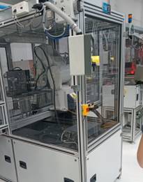
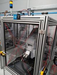
Fig.
1. Fencing of a robotic workplace Fig.
2. Fencing of a robotic workplace
The
problem arose on the part of the assembly line where the robotic arm is
installed behind the safety fencing (in the cage). According to the standards,
and the technical inspection, the given device is unsatisfactory from a safety
perspective; it is necessary to correct the current state, and only then can
the device obtain a CE certificate. The technical inspection does not give an
official permit for the operation of such equipment. Certificates according to
Act 124/2006 Coll. discuss the safety of technical equipment [20]. In Figures 1
and 2, it is possible to see three walls of the fences in the robotic workplace
in which a collision can occur. The result can be a fatal collision with the
person standing next to it.
Due
to various factors, a specific workplace creates danger for human operators,
which is an unacceptable situation from the position of safety and health at
work. The standard STN EN ISO 14121-1: 2008 deals with the assessment of risks
in all phases of the life of machinery. The functional safety of the machine is
discussed in STN EN ISO 13849-1: 2008 [30]. According to these standards,
equipment put into operation is not completely in order. The biggest problem is
that due to the spatial possibilities and the robotic arm used, there is still
the possibility of a collision with the protective fencing.
The
robotic arm used is from Mitsubishi, type RV-7FM-D1-S15, while cooperating with
the robotic controller type CR750-07VD1-1-S15. As part of the purchase of the
device from a subcontractor, it was possible to purchase a module to protect
the device from damage (possible collision) [31]. The function of this module
is to protect the device and prevent the robotic arm from moving out of its
confinement. Due to an insufficient budget, the purchase of this option was
rejected. Based on the customer's request, the concept of increasing the safety
of the robotic device was proposed. The TRIZ methodology proved to be very
reliable, not only in the phase of the ideological (conceptual) solution but
also in solving various technical problems and contradictions.
2. TRIZ METHODOLOGY AND PROBLEM SOLVING
Based on previous experience, the
TRIZ method has proved its worth in solving various problems, providing good
solutions to problems where technical or physical contradictions arise in
proposed solutions. The term contradiction can be understood that by increasing
the value of one parameter, we achieve a decrease in the value of another
parameter, which is important to us. This method is innovative and provides the
key to overcoming contradictions through various solutions [7, 32, 33].
The main problem solved was
insufficient safety of the working robot. Safety had to be increased, so the
question was "How?". When considering this problem, another condition
was encountered, and it sounded at least interfering with the existing
construction of the workplace [34, 35].
Using the TRIZ methodology, a key
technical discrepancy was determined, which arose from the relationship between
the stability of the building (fencing) - 13 and the adaptability of the
building (fencing) - 35 (Figure 3). By increasing the stability of the fence,
we can strengthen the fence, however, this makes it unable to adapt to a
possible impact. By increasing the adaptability, we can achieve low stability
of the building, that is, the fencing may withstand the impact; however, there
will be a deviation from the cage, which is unacceptable for technical
inspection (light gates - Section 1). According to Altshuller’s table,
the problem (contradiction) can be solved by several possible approaches,
namely flexible coatings or membranes (35), recycling and regeneration (34),
separation of the part (2), or change of physical or chemical properties (30).
The solution principle with flexible
coatings or membranes can be used to increase the safety of the device (35). An
example would be the use of impacting a panel of doors and walls covered with a
durable coating. Based on available resources, this principle cannot be used to
solve this situation, thus, a simple and effective solution is needed.
Fig. 3. Technical discrepancy of construction
in the Altshuller matrix
Another solution provided was the
use of recovery and recycling (34). This solution option is used, for example,
when one part of the whole (no longer needed part) evaporates, resp. disappears
during operation, or a regeneration and recovery process may occur. In our
case, the team of designers did not figure out how to solve the problem in this
way.
The third principle of solving our
problem is to separate the influencing part from the whole, to separate it (2).
An example is a compressor room, which due to noise from compressors and
vibrations, is separated from the consumer of compressed air while the person
only has a compressed air connection located next to him/her. There were no
ideas or feedback from the team to use this principle.
The last usable principle from the
Altshuller table was the principle of changing the physical state (30), for
example, a change to a gas or liquid, or a change in other physical properties.
Upon closer examination and consultation of the design team regarding this
principle, it was concluded that there is a possibility to increase the
flexibility of the fence, and at the same time, reinforce the fence with the
least possible intervention and the lowest possible production costs -
assembly. Based on another consultation, several variants of resolving the
situation were created.
Based on the information available
so far, several ideas have emerged on how to strengthen the structure and
create a stronger fence of the robotic arm, which would withstand a possible
collision. Thus, it has to be a simple, economically undemanding solution that
can be quickly implemented. Given the solution to the discrepancy from the
previous section, the design team tried to provide the necessary solutions to
the situation.
The first proposal was to simply
reinforce a given existing structure so that the existing window of the
structure and the door could be easily divided by a profile. This would create
reinforcement and require smaller plexiglass, which can effectively increase
the strength of the construction of all three walls-doors. From an economic
standpoint, it would be necessary either to buy new plexiglass or cut old
plexiglass to the required dimensions.
The second solution to the situation
was to double the plexiglass structure. Plexiglass would be attached to the
aluminium frame (BOSCH) via auxiliary plates, slotted nuts, and screws. The
advantage would be the creation of the second stage of fencing, which should
protect the environment from a possible collision with the robotic arm.
The third variant provided deals
with the doubling of plexiglass, and the two segments will be interconnected.
The design will create a second part of the fence, independent, but at the same
time connected to the first part, which will increase the strength of the
primary glass and, if possible, make the glass become a stronger and more rigid
unit.
2.2. Solution
The contracting authority had the
decisive word for the approval of the final solution. The provided solution
variants were subjected to a decision-making process by the customer. However,
a few pitfalls arose concerning the implementation of the first variant, and
the client disagreed with the dismantling of the assembled fencing. In the
second variant of the solution, there was no connection between the first and
second glass, which gave the impression that the added glass is only a kind of
"second safety glass", which in essence may not be enough in the
event of a possible collision.
The construction team agreed on the
use of the change in the physical properties of the structure (TRIZ) by
creating two segments of the protective fence and interconnecting them. The
third variant was chosen for the solution using the TRIZ method, which gave us
a strong solution to the technical conflict. A second glass was used, attached
to the first using manufactured spacer rings (2), washers (3), nuts (1), and
screws (4) (Figure 4).
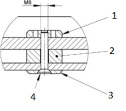
Fig. 4. Designed fencing reinforcement
To verify the data, and create the
basis for the technical inspection, it was necessary to verify the proposed
solution. The simulation took place in the Ansys Workbench program, addressed
in the following section (Section 3).
3. CONSTRAINTS AND FEM SIMULATION
This section deals mainly with
proving the effectiveness of solving the problem. Step one was the definition
and modelling of design modifications, coming to new conclusions, and
determining the key points of the design and possible variants of robot
failure. The situation of the device is as follows:
-
the device is
bounded on three sides by insufficient fencing;
-
two of these sides
are large openable windows for possible maintenance;
-
the filling
consists of a 10 mm thick polycarbonate board;
-
one side is a
solid (non-openable) polycarbonate sheet.
The design team agreed to modify the
equipment fencing as follows:
-
adding spacer
rings, nuts, washers, and screws to each endangered fencing wall and doubling
the protection by adding another polycarbonate panel (t = 6 mm);
-
addition of
security elements for locking the door (component made of polyamide PA6);
-
prescription of
the exact layout of individual spacer rings, locks, and hinges.
The simulation was performed in the
Ansys Workbench program.
3.1. Forces locations
Within the design
team, we wanted to determine the place of impact and the magnitude of the force
as the most critical points of the structure, that is, where the given fencing
elements will be most loaded. The most critical from this point of view was the
centre of the largest wall of the fence and the edges of the opening doors
Figures 5 and 6).
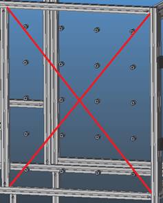
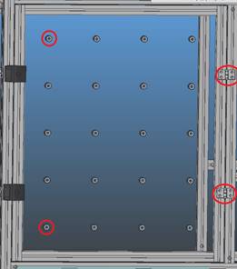
Fig.
5. Impact Glass (LH) Fig.
6. Impact to distant opera points
(reaction
in hinges)
The maximum load capacity can be
read from the graph and from the data on the robotic arm [36] where the
dependence of the distance of the centre of gravity of the robotic arm from the
distance of the centre of gravity of the manipulated load is plotted. If we
consider the problem as static, then we use the safety factor k = 3. If the arm
is the most loaded, that is, with the largest possible manipulated load (7 kg),
at max. distance r = 0.24 m, the force (formula 2) at the maximum speed on the
axis J6 (12.566 rad / s) is as follows:
![]() (1)
(1)
![]() (2)
(2)
The resulting impact force at safety
k = 3 could be obtained in the worst possible variant around 800 N when solved
as a static problem. The simulation was performed only by loading the specified
specific critical variants selected based on the previous risk analysis.
3.2. Forces on the side window (LH)
The method of impact can be seen in
Figure 5, where the robotic arm would in the worst possible conditions, strike
directly into the centre of the wall with the reinforcement already engaged.
The centre of the polycarbonate plate from the edges of the Al profiles has the
coordinates of the x-axis = 493.75 mm; y-axis = 596.5 mm.
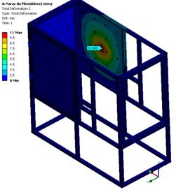
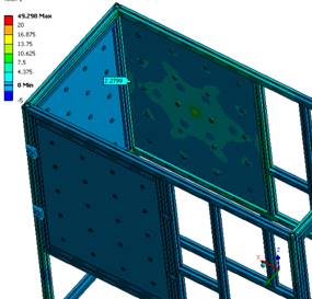
Fig. 7. Total deformation (LH) Fig.
8. Von Mises Stress (LH)
The resulting deflection and
stresses on the largest side of the protective fence are still within the
permissible stresses (49.3 MPa, Figure 8) because the maximum value of tensile
strength for the polycarbonate board is 60 MPa (70 MPa) [37]. The deflection
itself (Figure 7) is no longer large (11 mm) under the action of such a large
force on such a large area with such a thick glass. The assumption that a given
impact phenomenon occurs is small, with the robotic arm moving with much
smaller loads during line handling.
3.2. Forces on the side door (RH)
In Figure 6, it is possible to see
the critical points of application forces on the right side of the door. Hinges
and locks are important parts as the fencing door must remain in place for
safety, and protect its surroundings. Figure 6 shows possible points of
collision within the RH side and are the centres of the spacer rings. With the
correct placement, the impact in both variants should have approximately the
same course, therefore, the variant of the impact into the upper spacer ring
with the coordinates of the x-axis = 110.25 mm was chosen; y-axis = 981.7 mm
(from the edge of the Al profile). The entire closing of the door on this side
of the protective cage was solved using two locks made of PA6 and two hinges
made of Al from BOSCH.
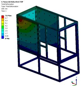
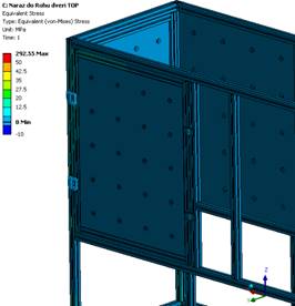
Fig. 9. Total deformation (RH). Fig.
10. Von Mises stress (RH)
In Figure 9, a maximum deviation of
7.6 mm was obtained, which is still at an acceptable value. According to the
simulation, Figure 10 shows a voltage of 292.55 MPa, which is an unacceptable value.
The given value, however, came out in the radii of the polyamide lock during
the testing, which the FEM method can cause stress concentrators to form within
the rounding (Figure 11). As for the reactions in the hinges, the largest
reaction in the hinge came out as 400.5 N in Figure 15. The most stressed was
the upper lock, which had the above-mentioned unacceptable value of von Mises
voltage. The yield strength of polyamide PA6 is 76 MPa [38].
When using the FEM method, it is
necessary to remove any rounding’s, as this rounding’s create
stress concentration. Most of the lock component is coloured in a less
pronounced green colour, which is a value of up to 47 MPa. The given value and
the colouring of the whole part indicate that the given part (tongue) should
withstand a possible collision with the robotic arm [39, 40]. The response in
the lock was calculated in the simulation to the value of 824.23 N, which the
lock bolts withstood in the verification calculation without major problems.
The simulation proved the necessary
results for the certification of the device. The report was forwarded to the
structural engineer for the safety assessment of the proposed fencing. The
structural engineer affirmed the report, which was subsequently submitted to the
technical inspection.
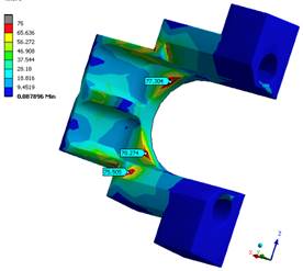
Fig. 11. The lock and von Mises
Stress
4. CONCLUSION
The essence of this article was to
introduce the reader to the solution to a security problem. In our case, a
systematic approach and the use of one of the known innovative methods –
TRIZ managed to get a suitable solution. The methodology is still used in large
design offices, where the team of designers also have an expert in this
methodology. The methodology can be used, not only for solving serious
innovative tasks but also for various technical problems, where the solution
lies in the correct definition of the problem. Further, this article gives an
example of how the design team proceeded to design safer fencing.
As part of solving a specific
problem of increasing safety, the team came up with a simple and effective
solution to increase the strength of the fence, without much intervention. The
provided solution was then simulated in the Ansys Workbench software, and
certain conclusions were drawn from it. Based on these conclusions, a report
was prepared for the structural engineer, who approved the results. Upon the
conclusions drawn, the technical inspection evaluated the proposed solution as
sufficient and, the equipment obtained a CE certificate after implementing the solution.
Source
of funding
This study was supported by the Cultural and
Educational Grant Agency MŠVVaŠ, under contract no. 015ŽU-4/2020
“Inovácie edukačného procesu s využitím
nových technológii v CAD”.
References
1.
Indri Marina, Luca
Lachello, Ivan Lazzero, Fiorella Sibona, Stefano Trapani. 2019. „Smart
Sensors Applications for a New Paradigm of a Production Line”. Sensors
19(3): 650. DOI: https://doi.org/10.3390/s19030650.
2.
Vaičekauskis
M., R. Gaidys, V. Ostaševičius. 2013. „Influence of boundary
conditions on the vibration modes of the smart turning tool”. Mechanika 3: 296-300.
3.
Rimkevičienė
J., V. Ostaševičius, V. Jūrėnas, R. Gaidys. 2009.
„Experiments and simulations of ultrasonically assisted turning
tool”. Mechanika 1: 42-46.
4.
Fomin Alexey, Wsevolod
Ivanov. 2019. „Development of a Mixing Mechanism with a Complex Motion of
the End-effector”. Strojniski Vestnik – Journal of Mechanical
Engineering 65(5): 319-325. ISSN: 2536-2948. DOI:
https://doi.org/10.5545/sv-jme.2018.5965.
5.
Khashayar Asadi,
Akshay Kalkunte Suresh, Alper Ender, Siddhesh Gotad, Suraj Maniyar, Smit
Anand, Tianfu Wu. 2020. „An integrated UGV-UAV system for construction site
data collection”. Automation in Construction 112: 103068. ISSN:
0926-5805. DOI: https://doi.org/10.1016/j.autcon.2019.103068.
6.
Belorit Michal,
Slavomir Hrcek, Tomas Gajdosik, Jan Steininger. 2017. „ Description of
the bearing check program for countershaft gearboxes”. ICMD 2017: 58th
International Conference of Machine-Design-Departments: 32-35. The Faculty
of Engineering, Czech University of Life Sciences Prague, Prague, Czech
Republic. 06-08 September 2017.
7.
Bistak Marek,
Stefan Medvecky, Slavomir Hrcek. 2017. „ The Above-ground
Weighbridge”. TRANSCOM 2017: 12th international scientific conference
of young scientists on sustainable, modern and safe transport: 52-57.
University of Zilina, Zilina, Slovak Republic. 31 May-02 June 2017. High Tatras
Slovak Republic.
8.
European Union,
EU. „CE marking”. Available at:
https://europa.eu/youreurope/business/product-requirements/labels-markings/ce-marking/index_en.htm.
9.
Terninko John,
Alla Zusman, Boris Zlotin. 1998. Systematic
Innovation: An Introduction to TRIZ (Theory of Inventive Problem Solving). Boca Raton, Florida: CRC Press.
ISBN-13: 978-1138440562.
10. Jiwen Chen, Xin Li, Hongjuan Yang, Chen Wang. 2019. „Innovative Design of a Vertical and Transverse
Elevator in Double Shafts, Based on TRIZ Theory”. Strojniski Vestnik – Journal of Mechanical
Engineering 65(5): 297-310. ISSN: 2536-2948.
DOI: https://doi.org/10.5545/sv-jme.2018.5937.
11. Leber Marjan, Majda Bastic, Borut Buchmeister. 2014. „The Trends in Usage and Barriers of Innovation
Management Techniques in New Product Development”. Strojniski Vestnik – Journal of Mechanical
Engineering 60(6): 382-388. ISSN: 2536-2948. DOI: https://doi.org/10.5545/sv-jme.2013.1611.
12. Mierczyk Zygmunt. 2012. „Lasers in the dual use technologies”. Bulletin of the Polish Academy of Sciences:
Technical Sciences 60(4): 691-696. ISSN: 2300-1917. DOI: https://doi.org/10.2478/v10175-012-0080-z.
13. Tian Xu, Jizhuang Fan, Qianqian Fang, Jie Zhao. 2019. „Robotic arm collision rteaction strategies for safe human-robot interaction without torque sensors”. Journal of
Mechanics in Medicine and Biology 19(7): 1940034. ISSN: 1793-6810.
DOI: https://doi.org/10.1142/s0219519419400347.
14. Liptakova Tatiana, Jozef Broncek, Martin Lovisek, Jan
Lago. 2016. „Tribological and corrosion properties of Al-brass”. 33rd
Danubia Adria Symposium on Advances in Experimental Mechanics: 5867-5871.
20-23 September, 2016. Portroz, Slovenia. ISSN: 2214-7853.
15. Zhen Xiao, Qun You Zhao, Fen Lin, Min Ming Zhu, Ji Yao
Deng. 2018. „Studying the Fatigue Life of a Non-pneumatic Wheel by
Using Finite-Life Design for Life Prediction”. Strojniski Vestnik - Journal of Mechanical
Engineering 64(1): 56-67. ISSN: 2536-2948. DOI:
https://doi.org/10.5545/sv-jme.2017.4695.
16. Steininger Jan, Slavomir Hrcek, Branislav Krchnavy.
2017. „ The design of universal loading device for a grinding
machines”. TRANSCOM 2017: 12th international scientific conference of
young scientists on sustainable, modern and safe transport: 869-874.
University of Zilina, Zilina, Slovak Republic. 31 May-02 June 2017.
17. Skyba Rudolf, Slavomir Hrcek, Lukas Smetanka, Maros
Majchrak. 2019. „Strength analysis of slewing bearings”. TRANSCOM
2019: 13th International Scientific Conference on Sustainable, Modern and Safe
Transport: 52-57. University of Zilina, Zilina, Slovak Republic. 31 May-02
June 2017.
18.
Stanczyk
Marcin, Tomasz Figlus. 2019. „The Effect of Selected Parameters of Vibro-Abrasive
Processing on the Surface Quality of Products Made of 6082 Aluminium
Alloy". Materials 12(14): 4117.
ISSN: 1996-1944. DOI: 10.3390/ma12244117.
19.
Figlus
Tomasz, Mateusz Koziol, Lukasz Kuczynski. 2019. „The Effect of
Selected Operational Factors on the Vibroactivity of Upper Gearbox Housings
Made of Composite Materials". Sensors 19(19): 4240.
ISSN: 1424-8220. DOI: 10.3390/s19194240.
20. Narodny
inspektorat prace. Kontrola pevne instalovanych pracovnych prostriedkov a
skusky tvarniacich strojov. [In Slovak:
National Labor Inspectorate. Inspection of permanently installed work
equipment and testing of forming machines]. Available at:
https://www.ip.gov.sk/kontrola-pevne-instalovanych-pracovnych-prostriedkov-skusky-tvarniacich-strojov/.
21. Wasim Ahmed Khan, Abdul Raouf. 2005. Standards for
Engineering Design and Manufacturing (Mechanical Engineering). Boca Raton,
Florida: CRC Press.
ISBN-13: 978-0824758875.
22. Jankech Peter, Peter Fabian, Jozef Broncek, Yuriy
Shalapko. 2016. „ Influence of Tempering on Mechanical Properties of
Induction Bents below 540°C”.
Acta Mechanica et Automatica 10(2): 81-86.
ISSN: 2300-5319. DOI: https://doi.org/10.1515/ama-2016-0013.
23. Daily Automation. „EN
ISO 10218 – Priemyselne roboty a ich integracia do priemyslu”. [In Slovak: Daily automation. „EN ISO 10218 – Industrial robots and their integration in industry”]. Available at:
https://www.dailyautomation.sk/priemyselne-roboticke-systemy-a-ich-integracia-do-priemyslu/.
24. Sarkan Branislav,
Andrzej Kuranc, Lubos Kucera. 2019.
„Calculations of exhaust emissions produced by vehicle with petrol engine
in urban area”. IV International
Conference of Computational Methods in Engineering Science – CMES'19.
Lublin University of Technology, Lublin. 21-23 November 2019. Kazimierz Dolny,
Poland. DOI: 10.1088/1757-899X/710/1/011001.
25. Kucera Lubos, Igor Gajdac, Peter Kamas. 2014. „ Computing
and Design of Electric Vehicles Modern methods of construction design”. ICMD 2013: 54th International Conference of
Machine-Design-Departments: 105-111. Faculty of Mechanical Engineering,
Technical University of Liberec, Liberec, Czech Republic.
10-12 September 2013. ISBN: 978-3-319-05202-1.
26. Galbavy Marian, Jaroslav Pitonak, Lubos Kucera. 2014.
„Powershift Differential Transmission with Three Flows of Power for
Hybrid Vehicles Modern methods of construction design”. ICMD 2013:
54th International Conference of Machine-Design-Departments: 27-33. Faculty of Mechanical
Engineering, Technical University of Liberec, Liberec, Czech Republic. 10-12
September 2013. ISBN: 978-3-319-05202-1.
27. Drbul Mario, Pavol Martikan, Jozef Broncek, Ivan
Litvaj, Jaroslava Svobodova. 2018. „Analysis of roughness profile on
curved surfaces”. ITEP´18 -
Innovative Technologies in Engineering Production. Faculty of Mechanical
Engineering, University of Zilina, Slovak Republic. 11-13. September 2018. ISSN:
2261-236X.
28. Euchner. EUCHNER – More than safety.
Available at:
https://www.euchner.de/de-de/produkte/multifunctional-gate-box-mgbs/komplettsets-mgbs-p-l-h/.
29. Kucera Lubos, Tomas Gajdosik. 2014. „ The
Vibrodiagnostics of Gears Modern methods of construction design”. ICMD
2013: 54th International Conference of Machine-Design-Departments: 113-118.
Faculty of Mechanical Engineering, Technical University of Liberec, Liberec,
Czech Republic. 10-12 September 2013. ISBN: 978-3-319-05202-1.
30. Steininger Jan, Slavomir Hrcek, Tomas Gajdosik, Marian
Stopka. 2017. „The optimization procedure of the inner geometry in
the spherical roller bearings with regard to their durability”. ICMD
2017: 58th International Conference of Machine-Design-Departments: 50-55. Faculty of Engineering,
Czech University of Life Sciences, Prague, Czech Republic. 06-08 September 2017.
31. Orman Lukasz J., Norbert Radek, Jozef Broncek. 2017. „Sintered Mesh Layers for the Production of Efficient Phase
– Change Heat Exchangers”. 10th Conference on Terotechnology:
189-193. Faculty of Materials Engineering and Metallurgy, Silesian
University of Technology, Katowice, Poland. 18-19 October 2017.
ISBN: 978-1-945291-80-7.
32. Mind Tools. „TRIZ - Creativity Techniques
From MindTools.com”. Available at:
https://www.mindtools.com/pages/article/newCT_92.htm.
33. Syed Ahmad Helmi, Arman Bin Alias, Muhammad Hisjam.
2018. „Improved design solution for motion resistance problem
through integration of robust design and theory of inventive problem solving
(TRIZ) principle”. 4th International conference on industrial,
mechanical, electrical and chemical engineering. Surakarta, Indonesia.
9-11 October 2018. ISBN: 978-0-7354-1827-1.
34. Kaplan Stan. 1996. An Introduction to TRIZ.
Farmington Hills, Michigan: Ideation Intl Inc. ISBN: 1-928747-0-00.
35. Broncek Jozef, Mário Drbúl, Michal
Stupavský, Norbert Radek. 2017. „ The application of new rules of
GPS in structural product requirement”. 58th International Conference of Machine-Design-Departments: 50-55.
Faculty of Mechanical Engineering, University of Zilina, Zilina, Slovak
Republic. 06-08 September 2017.
36. Mitsubishi Electric Corporation. „RV-4/7/13/20FM-D-SE Series Standard Specifications
Manual”. Available
at:
https://eu3a.mitsubishielectric.com/fa/en/dl/11035/e40e9916-473a-11ea-9f1a-b8ac6f83a177_bfp-a3322k.pdf.
37. Polycarbonate. Available at:
http://polymerdatabase.com/Commercial%20Polymers/PC.html.
38. PA6G - liaty polyamid TechPlasty. Available at:
https://www.techplasty.sk/material/polyamid/pa6g-liaty-polyamid.
39. Jambor Michal, Daniel Kajanek, Stanislava Fintova,
Jozef Broncek, Branislav Hadzima, Mario Guagliano, Sara Bagherifard. 2020.
„Directing Surface Functions by Inducing Ordered and Irregular
Morphologies at Single and Two‐Tiered Length
Scales”. Advanced Engineering Materials 2001057. DOI: https://doi.org/10.1002/adem.202001057.
40. Weis Peter, Lubos Kucera, Peter Pecha, Martin Mocilan.
2017. „Modal analysis of gearbox housing with applied load”. TRANSCOM
2017: 12th international scientific conference of young scientists on
sustainable, modern and safe transport: 953-958. University of Zilina, Zilina, Slovak Republic. 31
May-02 June 2017.
Received
08.02.2021; accepted in revised form 20.04.2021
![]()
Scientific Journal of Silesian University
of Technology. Series Transport is licensed under a Creative Commons
Attribution 4.0 International License