Article
citation information:
Fabiś, P., Flekiewicz, M. Optimalisation of the SI
engine timing advance fueled by LPG. Scientific
Journal of Silesian University of Technology. Series Transport. 2021, 111, 33-41. ISSN: 0209-3324. DOI: https://doi.org/10.20858/sjsutst.2021.111.3.
Paweł FABIŚ[1], Marek FLEKIEWICZ[2]
OPTIMALISATION
OF THE SI ENGINE TIMING ADVANCE
FUELED BY LPG
Summary. This study is an attempt to determine the control
parameters of the control system for gaseous fuels currently used for driving
vehicles. It presents the selected dynamic parameters of the car obtained when
fueling the engine with petroleum-based LPG. This paper attempts to determine
the optimal timing advance of the gas-air mixture and the efficiency of its
processing in the drive system of the tested vehicle driven by a four-cylinder
engine with a 1.6 dm. More
so, this article includes an analysis of the influence of the optimised power
charts of the engine on the dynamics of the motion of a motor vehicle running
on gaseous fuel. To present changes in the dynamics of movement, indicators and
parameters determining changes in the dynamics of vehicle movement, such as
dynamic coefficient, acceleration and flexibility were used. Through this
analysis, it is possible to verify the optimised power and torque waveform and
determine whether the vehicle dynamics improved.
Keywords: LPG, power charts, timing advance
1. INTRODUCTION
The achievement of low emissions in exhaust gases from
SI engines currently determines the development trends
of motor vehicles. These include both the introduction of new technical and
technological solutions in fuel injection systems, improvement of the
combustion process, exhaust gas cleaning systems, and the use of alternative
fuels. The advantage of using alternative fuels is, among other things, the
fact that the combustion engine driving the vehicle does not require major
modifications, and the existing infrastructure ensures the smooth supply of
these fuels. In addition, the currently applicable dual-fuel alternative
gasoline or LPG or CNG systems are solutions that increase vehicle autonomy,
considering its beneficial environmental aspects, it also ensures the economics
of operation due to the advantageous price ratio compared to gasoline [9, 10].
Despite the critical assessments of environment benefits resulting from the use
of alternative gaseous fuels, which appear in some scientific studies, most
vehicle manufacturers include them in the adopted development strategies of the
product being manufactured [1, 2]. This is also because currently available
technologies enable the production of these fuels from biomass, thus, qualifies
them for renewable fuels. Current LPG and CNG systems ensure relatively fast
adaptation of the vehicle to fuel with these fuels, and the results of their
tests, carried out following the requirements of UN / ECE Regulation 115,
confirm the reduction of CO2 emissions and controlled exhaust
components compared to the emission obtained for gasoline.
The scope of tests carried out following the
requirements of Regulation 115 does not specify dynamic indicators of a motor
vehicle, and in most publications, it presents only the maximum power achieved
by the engine or on the wheels of a motor vehicle. Hence, in this article,
tests were carried out aimed at comparing the influence of the ignition advance
angle on selected indicators characterising the vehicle performance. The basis
for calculations were the external characteristics of the Opel Astra 1.6
engine, which was powered by LPG. The engine and the fuel dose control system
did not introduce any changes, modifications were introduced in the management
of the ignition advance angle. Obtained results of the calculations explain the
effect of changes in the ignition advance angle on changes in the dynamics of
the tested vehicle.
2. TEST OBJECT
CHARACTERISTICS
The SI engine of the Opel Astra 1.6 was used in the
tests. Its basic technical parameters together with the characteristics of the
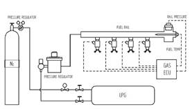
car are shown in Table 1. The engine was powered by LPG fuel, using independent
power supply systems, providing the engine with a mixture of liquefied gases
with a pressure not exceeding 0.5 MPa. The system provided a multi-point
injection of gaseous fuel, whereby the gas condensed after evaporation was
injected at a pressure of 10.0 kPa. The simplified block diagram of the system
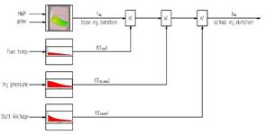
is shown in Figure 1. In contrast, Figure 2 explains how to control the dose of
gaseous fuel.
Based engine data characterised researched car shown in
Table 1.
The performance of the car was determined by analysing
its dynamic characteristics, expressing the dependence of power developed on
the wheels from the speed of the car, which was obtained using a Bosch FLA 203
chassis dynamometer. A simplified diagram of the position is shown in Figure 3.
Changes in the ignition advance angle were conducted using a programmable
computer allowing for changing the settings of the data at each engine work point
or within a specified range. Further, the test stand was equipped with
transducers and sensors that ensure the identification of the engine's
operating status. The basic control and measurement systems ensuring continuous
recording of the engine operation state were, inter alia, devices enabling
measurement of:
• pressure in the engine cylinders,
• angle of rotation of the crankshaft with the
determination of the piston GMP,
• power developed on the wheels of the tested car,
• negative pressure prevailing in the intake
manifold,
• temperature of the intake air and exhaust gases.
|
|
|
|
Fig. 1. Scheme of operating system [9] |
Fig. 2. Scheme of engine control system [9] |
Tab. 1
Based parameters of the car engine
|
Number
of cylinders |
4 R |
|
Maximum
power and RPM |
55 kW /
5200 1/min |
|
Maximum
torque and RPM |
128 Nm /
2800 1/min |
|
Capacity |
1598 cm3 |
|
Diameter |
79.0 mm |
|
Stroke |
81.5 mm |
|
Compresion
ratio |
9.6 |
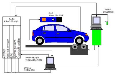
Fig. 3. Scheme of testing stand [9]
The pressure inside the cylinder was measured using a 6121 piezoelectric pressure sensor and KISTLER type 5011 charge amplifier. The position of the crankshaft and its rotational speed were determined using the KISTLER type 2613B crankshaft position marker. This transducer is an integral part of the gasoline fuel dose management system, injected into the intake manifold of the tested car's engine.
The mass flow of gaseous fuel flowing into the engine power system was measured using a precision tensometric weight. All measured parameters were recorded and visualised using the NI PCI-6143 data acquisition card and a proprietary program developed in the environment LabView 7.1.
3. RESULTS AN
DISCUSSION
3.1. Power and torque results
The results of power and torque measurements developed by the car engine, fueled by LPG at various ignition timing angles, are presented in Table 2, and the course of changes in power and torque depending on the engine speed is shown in Figure 4.
Tab. 2
Power and torque received during dynamometers test
|
L.p. |
Fuel and CA change |
Power [kW] |
nN [min-1] |
Torque [Nm] |
nM [min-1] |
|
1 |
LPG 0CA |
55,02 |
5051 |
125,19 |
3337 |
|
2 |
LPG +3CA |
54,55 |
4812 |
125,96 |
3288 |
|
3 |
LPG +6CA |
54,34 |
5190 |
126,08 |
2889 |
|
4 |
LPG -2CA |
55,07 |
5210 |
125,06 |
3367 |
|
5 |
LPG opt |
56,27 |
5091 |
132,55 |
2600 |
The obtained results indicate a clear change in the
engine power and torque depending on the ignition advance angle in the gas
mixture feeding the engine. By increasing the lead in the ignition angle, the
maximum power and torque are reduced. If the value of the ignition advance
angle is reduced, a clear increase in the maximum power value is observed. The
situation changes dramatically when the ignition advance angle is optimised and
values changing the torque and power curve in specific speed ranges are
introduced. In the 1000 - 2500 min-1 speed range, an angle of + 6st has been
entered, in the range of 2,500 - 4,500 min-1 an angle of + 3 degrees has been
introduced, while in the range above 4500 min-1 an angle of -2st has been
introduced. When using such an optimised ignition angle, a distinct change in
the external motor characteristics is obtained.
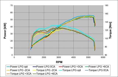
Fig. 4. Performance characteristics of
engine powered by LPG
with different crank angle set up
3.2. Method for fast determination of a
dynamic factor and vehicle acceleration
The dynamic properties of the car are compared using technical indicators expressing unit power, force or mass values. However, the dynamic indicator is usually used in the lowest and highest gears. It is the most universal indicator defining the car's engine properties, for example, climbing ability, ability to accelerate and overcome road resistance. This ratio is expressed as the following relationship:
|
|
(1) |

where:
Temax –
engine max torque, Nm,
io – final
drive ratio,
ig – gear
ratio,
Fa
– Air resistance force, N,
hm – mechanical efficiency of the transmission drive,
W – Total vehicle
weight, [N],
rd – dynamic
radius of the wheel, N.
Usually, its value is determined in the highest gear. Figure 5 shows the dynamic coefficient waveforms for different values of the ignition advance angle and the mileage optimised.
Acceleration of the vehicle in a particular
gear (ai) can be calculated from the following expression:
|
|
(2) |
where:
g – acceleration of g-force,
Di – dynamic factor
(characteristic) in a particular gear,
f – rolling resistance
coefficient,
di – rotating masses influence coefficient.
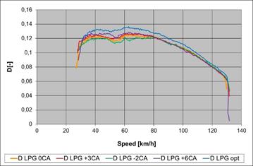
Fig. 5. Dynamic
factor characteristics of engine powered by LPG
with various timing advance
The analysis of the
results from the above figure shows that LPG with optimalised crank angle gave
higher car dynamics than the rest set angles. The difference between the fuels
is clearly visible in the whole range of car speed. It is caused by the
different crank angle set up for different rpm range as shown above.
Figure 6 shows the engine flexibility as a supplement describing the change in the car dynamics.
Described engine
flexibility at some part of range is the same value as a dynamic factor as seen
in Figure 7. The exception is the higher value of flexibility optimalisation
LPG fuel with corrected spark timing.
4.
CONCLUSIONS
Researches on the
use of vehicle feed LPG fuel allowed describing how the kind of engine
parameter includes car dynamic. Due to the description of done dyno test which
given power and torque engine allows calculation of dynamic factor,
accelerations and flexibility. Certified that the crank angle timing influences
the maximum power and torque value. An appropriately set crank angle timing is
given the torque and power increase. Set one timing angle for whole rpm range
improves the torque and power value only for the chosen range. This is the
reason for the optimalisation of the crank angle timing for the whole rpm range
as it improves its given power and torque at all range. Proposed value of
timing angle optimalising and improve the course of power and torque. For the
proposed timing angle value (+6°CA, +3°CA and -2°CA), power
increased over 1 kW and torque over 7 Nm.
|
a) |
|
|
|
b) |
|
|
|
Fig. 6. Acceleration characteristics of engine powered by LPG with various timing advance, a) lowest gear, b) highest gear |
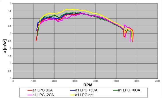
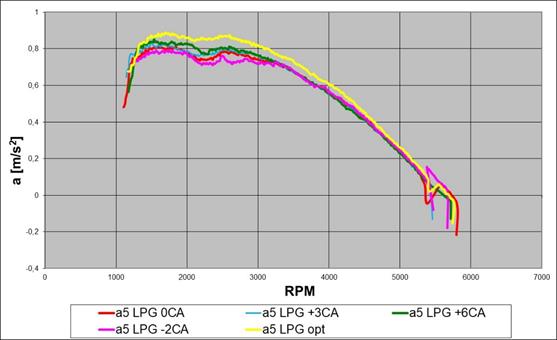
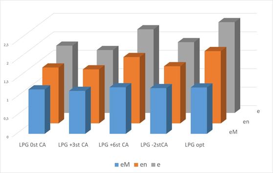
Fig. 7. Flexibility
of engine powered by LPG fuels for different crank angle set up
References
1.
Merkisz J., S. Radzimirski. 2006.
„Does the propane-buthane gas is an
ecological fuel?” Internal
Combustion Engines 2(125).
2.
Toyota's Strategy for Environmental Technologies.
Available at:
http://www.toyota-global.com/innovation/environmental_technology/strategy_environmental_tech.html.
3.
PZPM Raport. 2013.
4.
Van Mierlo J., G. Vereecken, G. Maggetto, V. Farrel, S. Meyer,
W. Hecq. 2003. „Comparizon of the
Environmental Damage Caused by Vehicles with Different Alternative Fuels and
Drivetrains in a Brusells Context”. J.
Automotive Eng. Proc. IMechE Part D
217(D7): 583-594.
5.
Campbell M., Ł.P. Wyszyński, R. Stone. 2004. „Combustion of LPG
in a Spark-Ignition Engine”. SAE
Paper 2004-01-0974.
6.
Fabiś P. 2005 „Measuring the indicated pressure and engine
block vibration – conception of the test stand”. XXXII National Symphosium of the Machine Diagnostic. Węgierska
Górka, Poland.
7.
Heywood J.B. 1998. Internal
combustion engines fundamentals. McGraw-Hill. New York.
8.
Rogers D.R. 2010. Engine
Combustion: Pressure Measurement and Analysis. SAE International.
9.
Usman M., N. Hayat. 2020. „Lubrication, emission and performance analyses of LPG
and petrol in a motorbike engine: a comparative study”. Journal of the Chinese Institute of
Engineers 43(1): 47-57. Available at:
https://doi.org/10.1080/02533839.2019.1676656.
10.
Simsek S., S. Uslu. 2020. „Investigation of the impacts of gasoline,
biogas and LPG fuels on engine performance and exhaust emissions in different
throttle positions on SI engine”. Fuel 279: 118528. DOI:
https://doi.org/10.1016/j.fuel.2020.118528.
Received 12.02.2021; accepted in revised form 27.04.2021
![]()
Scientific
Journal of Silesian University of Technology. Series Transport is licensed
under a Creative Commons Attribution 4.0 International License