Article
citation information:
Hrabovský, L. Tension force equalizer
in a rope system using a proximity sensor. Scientific
Journal of Silesian University of Technology. Series Transport. 2021, 110, 35-44. ISSN: 0209-3324. DOI: https://doi.org/10.20858/sjsutst.2021.110.3.
Leopold
HRABOVSKÝ[1]
TENSION
FORCE EQUALIZER IN A ROPE SYSTEM USING A PROXIMITY SENSOR
Summary. Different values of
tension forces in the load-bearing ropes of elevators, which push the rope into
the grooves of the traction discs with different pressure, are the cause of
uneven wear of the grooves of the traction discs under operating conditions.
Current technical standards in the EU stipulate that the load suspended on
load-bearing ropes be evenly distributed to all ropes used, using one of the
many construction designs for tension force equalizers in the rope system. The
main subject and primary objective of this paper are to present the
construction design, 3D model and produced device of one of four produced
prototypes, which were constructed in the “Research and Testing
Laboratory”, and allow setting of differing values of tension forces in
the system of ropes of a traction elevator, to values of the same size.
Laboratory measurements were performed on the produced device, which enables
the detection of tension forces in ropes and the magnitude of these forces in
the required period to be graphically displayed on a PC. The prototype
tension force equalizer can show the functionality and practical applicability
of the procedure of balancing the levels of tension forces, which are of
unequal strengths at the start of the laboratory measurement.
Keywords: tension force equalizer, rope elevator,
load-bearing rope,
ring load cell
1. INTRODUCTION
In practice,
the elevator car must be allowed to travel as high as possible in the elevator
shaft. This is ensured by installing the load-bearing rope bracket at the
shortest possible distance from the ceiling of the elevator shaft. The minimum
distance of the upper surface of the bracket from the ceiling of the elevator
shaft places a fundamental requirement on the design height of tension force
equalizers, which are installed at the ends of the threaded parts of the suspension
bolts. Mobile tension force equalizers have relatively large heights and their
use to balance varying tension forces to the same magnitude in a rope system is
not always suitable in cases where there is a lack of operating space and the
construction height is limited.
This paper
presents a sequence of activities and a description of the operations, which
when using a tension force equalizer, result in the weight of the load (in the
more loaded branch of the rope system of the elevator) in the final phase of
the experiment being evenly distributed in all cross-sections of the
load-bearing ropes.
The principles
of tension force equalizers suitable for use in cases of restricted operating
spaces and low ceiling height in the elevator shaft are introduced in [3,5].
2. Construction Design of
the Described Device
A 2D
construction design (created in AutoCAD) is presented in Fig. 1a. Fig. 2 shows
a 3D model created in the SolidWorks 2012 x 64 SP 5.0 environment, one of four
variants of a tension force equalizer in a rope system, which was designed and
assembled at the Institute of Transport, Faculty Mechanical Engineering, VSB -
Technical University of Ostrava, based on a requirement for its production by LIFTCOMP,
a. s.
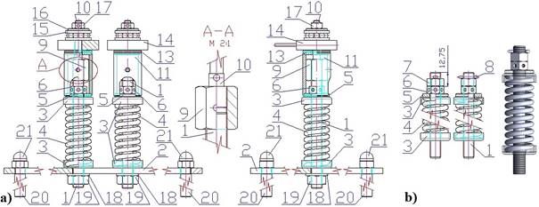
Fig. 1. a) 2D construction design for a tension force equalizer
in a system of ropes, b) terminal point of the suspension bolt in practice
The shanks (f 10 or 12 mm) of the suspension eyebolts 1 [1] pass
through (f 11 or 13.5 mm) in the bracket, which under laboratory
conditions is replaced by a steel plate (300 x 200 x 5 mm) 2, Fig. 1a. A bowl 3
and a compression coil spring 4 [7] are slid on the threaded part of each of
the eyebolts 1, which are threaded through the holes in the plate 2. A bowl 3,
a washer 5 and a hexagonal nut 6 are mounted on the upper end face of the coil
spring 4. In practice, unscrewing the nut 6 is prevented by the lock nut 7 and
the cotter pin 8 (Fig. 1b).
Holes (2.5 mm)
are drilled in the shank of the suspension bolts 1, their horizontal axes are
spaced at least 4.5 mm from the end faces of the shanks of the suspension bolts
1 (Fig. 1b). The minimum distance between the upper surface of the nut 6 and
the upper surface of the shank of the hinge screw 1 (after removing the cotter
pin 8 from the hole in the shank of the hinge screw 1 and unscrewing the lock
nut 7) is Lmin = 12.75 mm, Fig. 2b. The space Lmin
[m] is sufficient to
install the tension force equalizer.
A nut 9 (M10),
which has a hole (3 mm) formed on one of its vertical surfaces in the middle of
its height of 20 mm, is screwed onto the threaded part of the shank of the
suspension bolts 1. A threaded part (length 10 mm) of the pin 10 is screwed
onto the internal thread M10 of the opposite hole in the nut 9. A tubular part
11 is threaded on the pin 10 to form concentric holes (3 mm in the nut and 4 mm
in the tubular part 11). In the upper and lower part of the tubular part 11
(with an inner/outer diameter of 20/26 mm), an inner fitting is formed, the
so-called inner f 24 mm to a depth of 2 mm. The tubular part 11 is
threaded at the bottom onto the outer diameter (f 24 mm) of the washer 12 (height 3 mm). A ring 13
(with an inner hole of f 8 mm for the pin 10) is threaded on the inner fitting
(f 24 mm, depth
2 mm). A tension force sensor (Ring Load Cell) 14 (with an inner/outer diameter of 7/38 mm) is
threaded on the pin 10.
An axial
bearing (type 51100 ČSN 024730) 15 and a ring 16 (with an inner hole 6 mm
for the pin 10, with an outer 10 mm lower part 5 mm long, which is pushed into
the hole of the upper ring of the axial bearing 15 are mounted on the shaft of
the pin 10. Part of the height of the 2-mm ring 16 is 20 mm). An M6 nut 17 is
screwed onto the thread M6 in the end part of the pin 10.
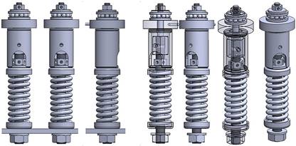
Fig. 2. 3D
model a tension force equalizer in a
system of ropes
The test device, Fig. 1 and Fig. 4, uses compression
coil springs 4 [7] with wire diameter d = 4 mm, outer diameter D1
= 24 mm, length in free state L0 = 63 mm, length in
retracted state L8 = 48.5 mm, total number of turns z =
10.5., number of active coils n = 8.5, spring force in retracted
state F8 = 549 N and stiffness (spring force when compressed
by 1 mm) c = 37.88 N/mm.
3. Aspects Equalizing Tension Forces in a Rope System
The load capacity Q [kg] of a passenger elevator is determined according to the
table in ČSN EN 81-20 [2]. The basic indicator for determining the load
capacity of a passenger elevator is the floor area of the cage, from which the
load capacity and the number of people who can use the elevator at one time are
calculated.
Elevator
cages must be suspended on either steel ropes, gall or roller chains. Steel
wire ropes must meet the requirements [2]: the nominal diameter must be at
least 8 mm; the nominal tension strength of the wires must be 1570 N·mm-2
or 1770 N·mm-2 for ropes with wires of the same tension
strength, or 1370 N·mm-2 for outer wires and 1770 N·mm-2
for inner wires for ropes with two nominal tension strengths; at least two
ropes must be used. The safety factor ks
[-] (is the ratio between
the guaranteed load capacity of the rope NL [N] and the maximum force FL [N] in this rope when the cage with
the rated load is at the lower end station) must not be less than 12 for a
drive with friction discs with three or more supporting ropes; 16 for a drive
with friction discs with two support ropes.
If the load capacity
of the lift is Q [kg],
the actual weight of the cage P [kg],
the height of the lift of the cage H [m], the rope gear r [-], the weight of the rope mL [kg·m-1],
the number of load-bearing ropes nL [-], then the greatest force FL [N] acting in one rope can be expressed
according to (1).
 (1)
(1)
If the
coefficient of the minimum breaking force ku
[-] and the minimum breaking force of the rope is NL
[N], then the safety factor of the rope ks
[-] can be expressed by the relation (2).
![]() (2)
(2)
By
modifying the relationships (1) and (2), it is possible to calculate the
required number of load-bearing ropes nL [-], relationship (3).
 (3)
(3)
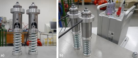
Fig. 3. Laboratory
model of described variants of a tension force equalizer in
a system of ropes, a) front view, b) rear view
The
principle, presentation and verification of the correct functionality of
equalizing tension forces in the system of ropes (which consists of two or more
ropes) is performed on devices assembled in the Research and Testing Laboratory
of the Institute of Transport, VSB-Technical
University of Ostrava, the equalizers tension forces in the rope system,
Fig. 3 and Fig. 5. The executed device is designed so that it has (for
reasons of reduction of economic costs used for the building of the laboratory
model and the purchase of a larger number of tension force sensors 14) only two
suspension bolts 1.
The cable ends
of both tension force sensors 14 are soldered to the connectors of the
“D Sub” connector plug. The connector plugs are plugged into
two of the four sockets in the DEWESoft DS-NET [6] measuring system. The DEWESoft
DS-NET measuring apparatus is connected to a PC with a network cable (with an
“RJ45” connector at both ends). In the DEWESoft X2 SP5 software
environment in the PC, the curves of the applied forces FL(i) [N] (initially different tension force magnitudes to tension
forces balanced to equal magnitudes) in the suspension bolts 1 were displayed
(detected by force sensors 14), Fig. 5.
The
different magnitudes of the initial values of the tension forces FL(i) [N] in the load-bearing ropes are derived by the different tightening of the
nuts 19, Fig. 1 and Fig. 4. Varied tightening of the nuts 19 causes a different
deformation (that is, compression H1(i)
[m]) of the compression springs 4.
Compression H1(i) [m] of the compression springs 4 is of the same magnitude as the vertical
displacement y1(i)
[m] of the nut 19. The magnitude of the
displacement y1(i)
[m] of the nut 19 can be expressed by the
relation (4), where ds [m] is the mean thread diameter of the hinge screw 1, a [deg] is the pitch angle of the thread of the suspension bolt 1, b [deg] is the angle of rotation of the nut
19, P [m] is the pitch
of the thread of the suspension bolt 1 and the nut 19.
![]() (4)
(4)
The lengths L1(i)
[m] (L1(2) on Fig.
4) compressed springs 4 (loaded by
forces FL(i) [N]) can be expressed
according to (5).
![]() (5)
(5)
Compressive
forces F1(i) [N]
acting in the springs 4; equal to the values of tension forces FL(i)
[N] in the load-bearing
ropes (6); are transmitted to the lower surfaces of the tension force sensors
14 via the washers 5, the tubular parts 11 and the rings 13.
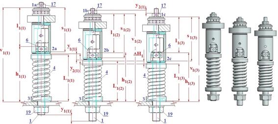
Fig. 4. Visualisation
of the action of balancing differing tension force magnitudes in
the ropes to a unified value.
![]() (6)
(6)
Compressive
forces Fc(i) [N],
which are the same magnitude as the compressive forces F1(i) [N], are applied to the upper
surfaces of the tension force sensors 14 (tension forces FL(i) [N] (1) are transmitted from the
load-bearing ropes via pin 10) (assuming tightened nuts 6).
If the nuts 17
are tightened, the distance l1(i) [m] is shortened (from the initial value l1(2) [m] to the value l1(3) [m], Fig. 4) and there is a vertical
displacement (relative to the upper surface of the suspension bracket, section
“3” in Fig. 4) of the suspension bolt 1 (provided that the nut 19
is not screwed onto the threaded part of the suspension bolt 1). In practice,
each of the suspension bolts 1 is subjected to a proportional part of the load
(ideally FL(1) = FL(2) = FL [N] (1)) and these loads (tension
forces in ropes FL(i) [N])
compress the springs 4. Further, if the magnitudes of the forces in the ropes FL(i)
[N] are not the same, the
springs 4 are deformed differently. The spring 4 which is most compressed H1(i)
[m] (that is, which has the
smallest height L1(i) [m])
generates the highest compressive force F1(i) [N] (6).
By tightening
the nut 17 of the least compressed H1(i) [m] spring 4, in the practical use of
the elevator, the vertical screw 1 is first shifted vertically, to which is
attached (least loaded by the force FL(i) [N] (6)) load-bearing rope. In this
load-bearing rope, the tensile force FL(i) [N] increases (because by shortening
the length of the rope, this rope is loaded with a larger proportion of the
load distributed into the rope system) and the spring 4 is compressed.
4.
Action of the laboratory model of the tension force equalizer
Tightening the
nut 17 of the least compressed H1(i) [m] spring 4 in the laboratory model (Fig. 3) results in (as
a result of the vertical shift y2(i) [m] (4) (Fig. 4) of nut 17, where ds [m] is the mean thread diameter of the
hinge screw 10, a [deg] is the pitch angle of the thread of
the suspension bolt 10, b [deg] is the angle of rotation of the nut
17, P [m] is the pitch
of the thread of the suspension bolt 10 and the nut 17) the transfer of the derived compressive force F2(i)
[N] on the spring 4, which,
due to increasing compressive forces F2(i) [N], is compressed (relative to the
uncompressed length L1(i) [m] of the spring 4 compressed by the force F1(i) [N]) after the completion of the
tightening phase of the nut 19 by the total size y2(i) [m] (7), and with respect to the
uncompressed length L0 [m]
of the spring 4 compressed by the total size sp(i) [m] (8).
![]() (7)
(7)
The increase
in compression DH(i) [m] of the spring 4 (at the moment of terminating
the tightening of the nut 17) is equal to the vertical shift y2(i)
[m] of the nut 17 being
tightened.
The total
compression sp(i) [m]
(8) of the spring 4 is equal to the sum of the vertical shift y1(i)
[m] of the nut 19 being
tightened and the vertical shift y2(i) [m] of the nut 17 being tightened.
![]() (8)
(8)
The resulting
lengths Lv(i) [m] (L1(3) on Fig. 4) of the compressed springs 4 (weighted with the
forces F2(i) [N]) can be expressed
according to (9).
![]() (9)
(9)
By tightening
the nut 17, the distance l1(i) [m] (l1(3) on Fig. 4) is shortened. For the
distance l1(i) [m]
according to Fig. 4, (10) applies.
![]() (10)
(10)
Given the
unchanging heights of the machine parts 6, 11 to 16 (Fig. 1a), when the nut 17
is tightened, a vertical shift of the nut 6 takes place (since the pin 10 is of
a constant and unchanging length) as well as the compression of spring 4 by a
value of y2(i) [m].
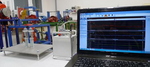
Fig. 5. Physical
execution of the model on a tension force equalizer in a system of ropes
If the nut 6
is rotated in the desired direction, at some point, the nut 6 rests on the
washer 5. By further turning the nut 6, the spring 4 is compressed by the value
H3(i) [m].
Compressing the spring 4 by the value H3(i) [m] produces a tension force F3(i
[N] in the suspension screw
1 and the pin 10, which is transmitted to the upper surface of the force sensor
14. Vertical displacement y3(i) = H3(i) [m], derived by turning the matrix 6,
causes the points “1c - 2c” to be delayed, that is, extension of
the length l1(i) [m],
which is given by the sum of the heights of the machine parts 6, 11 to 16,
and reduction of the compressive force F1(i) [N] acting on the force sensors 14.
Sizes of compressive forces F1(i) [N] acting on the force sensors 14, which are mounted on the
suspension bolts 1 of all load-bearing ropes for the given traction lift,
are displayed on the PC monitor. By gradually turning the nuts 6, the
tension forces in the ropes are balanced.
5. Experimental Tests
Cables
terminated with connectors of both tension force sensors 14 of the tension
force equalizer (Fig. 3b) for the test device (Fig. 5) were connected to the
measuring apparatus.
The data
(detected by the force transducers 14) was transferred to the PC via network
cable.
In the
DEWESoft X2 SP5 software environment, the waveforms of the detected compressive
force magnitudes FL(i) [N],
(Fig. 6) were displayed on the PC monitor.
Tab. 1 shows
the theoretically calculated compression force magnitudes Fl(i) [N] according to the relationship
(6), during the compression H1(i) [N] of springs 4 for both tension force equalizers.
Tab. 1
simultaneously gives the tensile force magnitudes FL(i) [N] that were detected by the tension
force transducers 14 during the gradual compression of the springs 4 and
subtracted from the PC monitor.
Fig. 6 shows
the waveforms of the measured forces FL(i) [N] detected by the force transducers
14. From Fig. 6, it is clear that the initially different magnitudes of tensile
forces in the ropes FL(i) [N] can be set to magnitudes of the same size by the tensile
force compensator, using the procedure described in the section
“Action of the laboratory model of the tension force equalizer”.
Tab.
1
Theoretically calculated and measurement-obtained
compression forces
|
F1(1) |
F1(2) |
H1(1) |
H1(2) |
L1(1) |
L1(2) |
FL(1) |
FL(2) |
|
N |
mm |
N |
|||||
|
75.76 |
151.52 |
2 |
4 |
61 |
59 |
78.16 |
147.93 |
|
151.52 |
227.28 |
4 |
6 |
59 |
57 |
157.37 |
232.44 |
|
227.28 |
303.04 |
6 |
8 |
57 |
55 |
223.28 |
310.34 |
|
303.04 |
378.80 |
8 |
10 |
55 |
53 |
305.63 |
365.88 |
|
378.80 |
454.56 |
10 |
12 |
53 |
51 |
382.35 |
462.11 |
|
454.56 |
530.32 |
12 |
14 |
51 |
49 |
467.71 |
526.59 |
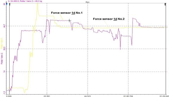
Fig.
6. The
holding force of the electromagnet depending on
the distance from ferromagnetic plate
6.
CONCLUSION
Construction
designs and principles of operation of technical devices as well as the
sequence of work procedures, by which the total weight of the load can be
evenly distributed into the partial cross-sections of load-bearing ropes,
which form the system of ropes in traction elevators, are presented in several
researches. These technical devices are called “elevator rope tension
force equalizers”.
The possible way of achieving uniform load
distribution into two or more carrier ropes in the traction lift using a tension force equalizer in a rope system with a proximity
sensor is given in this paper.
This device is portable and is mounted on suspension
bolts only when it is necessary to set the same tensile forces in carrier
ropes. After carrying out its activities, it is possible to remove the device
from the suspension bolts and move it to another traction rope lift.
In
contrast to the known principle of the hydraulic compensator [8], the described
device can be provided with strain gauge load cells that can detect
instantaneous tensile forces in carrier cables, record them and use them for
certificate processing purposes.
This paper
presents a technical design of a mobile, mechanical equalizer, which uses a
tensile force sensor (transducer) to detect tension forces in the ropes.
More so, this
paper presents a construction design and specifications of individual basic
components from which the equalizer is assembled. A 3D model of the tension
force equalizer in a system of ropes was presented as well.
The described device can
adjust the tension forces in the cross-sections of load-bearing ropes, either
during the installation of new elevators or reconstructions and upgrades of
existing elevators. This tension equalizer helps to extend the life of elevator
parts, that is, the load-bearing ropes and the rope friction disc.
The actual prestressing in the
ropes is measured by a sensor, which allows even distribution of the weight of
the load, and thus, distribute it appropriately into the partial cross-sections
of the load-bearing elevator ropes used. The measurement of the magnitude of
tension forces in ropes and their equalization can similarly take place even
during the operation of the elevator car. Tension compensation in load-bearing
ropes of elevators can be achieved using a mobile device to which the cross-sections
of the load-bearing ropes are attached.
The main
advantage of the device is the continuous measurement of the tension of all
ropes of the elevator system during the operation of the elevator. Other
advantages include a non-destructive method of monitoring the tension in the
ropes, that is, a method that does not require interruption of the final length
of the load-bearing rope on which the elevator car is suspended. Further
advantages are the simplicity of installation, affordability, low weight, the
possibility of various forms of measurement and the fact that the device has
its own battery power source.
Acknowledgements
This work was supported by the Ministry of Education,
Youth and Sports of the Czech Republic from the Specific Research Project
SP2020/90.
References
1.
Molnár
Vieroslav, Gabriel Fedorko, Jozef Krešák, Pavel Peterka, Jana
Fabianová. 2017. „The influence of corrosion on the life of steel
ropes and prediction of their decommissioning”. Engineering Failure Analysis 74: 119-132. ISSN: 1350-6307.
DOI: 10.1016/j.engfailanal.2017.01.010.
2.
Zajicek
Jiri. 2015. ČSN EN 81-20 „Bezpečnostní předpisy pro
konstrukci a montáž výtahů - Výtahy pro dopravu
osob a nákladů - Část 20: Výtahy pro dopravu
osob a osob a nákladů”. [In Czech: ČSN EN 81-20 „Safety
rules for the construction and installation of lifts - Lifts for the transport
of persons and goods - Part 20: Passenger and goods passenger lifts”]. 2015.
3.
wurtec. Available at: https://www.wurtec.com/cs/content/permanent-overload-sensor-system-rc-donut.
4.
Meatest.
Available at: https://www.meatest.com/cs/produkty-8438-prstencovy-snimac-tahove-a-tlakove-sily-detail-67.
5.
Rope Tension Adjustment Kit. Available at: https://www.youtube.com/watch?v=3bfKXDsEFy8.
6.
SENSING. Available at:
https://sensores-de-medida.es/medicion/sensores-y-transductores/celulas-de-carga/celulas-de-carga-tipo-arandela/.
7.
UVB
TECHNIK. Available at: http://www.uvbtechnik.cz/data/files/katalog-tlacnych-pruzin-31.pdf.
8.
Brugg
Lifting. Available at: https://brugg-elevator.com/static/document/RLE_Manual. pdf.
Received 26.07.2020; accepted in revised form 30.10.2020
![]()
Scientific
Journal of Silesian University of Technology. Series Transport is licensed
under a Creative Commons Attribution 4.0 International License