Article
citation information:
Kiedrowski, J., Jendro, G.,
Kamiński, A., Fabiś, P. Aerodynamics package for formula student car WT-02. Scientific Journal of Silesian University of
Technology. Series Transport. 2020, 109,
55-60. ISSN: 0209-3324. DOI: https://doi.org/10.20858/sjsutst.2020.109.5.
Jakub KIEDROWSKI[1],
Grzegorz JENDRO[2],
Arkadiusz KAMIŃSKI[3],
Paweł FABIŚ[4]
AERODYNAMICS
PACKAGE FOR FORMULA STUDENT CAR WT-02
Summary. This paper is a summary
of the design and workmanship of the aero package vehicle Formula Student. Simulation research projects of the
aerodynamic system were conducted. The article proposes different variants of the
aero wings and conducted simulation studies of construction. The aerodynamics
system impact on strength and reliability of selected models was determined.
Keywords: Formula Student, aero pack, MES, simulation
1. INTRODUCTION
Formula Student (FS) is an
international competition between teams of universities and technical faculties
from around the world organised in Europe by IMechE. The idea behind the
competition is to design and execute a racing vehicle in accordance with the
rules of the competition. The creation of the team finished the car in given
time and in line with the need to gain the knowledge, discipline, cooperation,
foresight, and often compromises. Experience and knowledge gained in such
circumstances are invaluable and an important part of training top-notch
engineers. Undoubtedly, this is also a chance to test their skills in the real
world, under the pressure of time and project requirements. Of importance is
not only the designed maximum speed of the car but the balance between a number
of important elements to be taken into speed, economy of operation, aesthetics,
functionality and safety. The victory in the competition is only for those
teams that are able to give a complete project and get it for the highest
number of points. With the FS, students have the chance to establish contacts
with the local industry, and the industry has the opportunity to support the
development of its potential future executives. The basis for the formula
student undoubtedly is the idea of supporting the development of technical
ideas. It shows the importance of creating technical universities. Engineering
studies and profession play a huge role in human development, therefore, are of
great value to society.
2. VEHICLE AERODYNAMICS
During its movement, a car vehicle is loaded with forces
from flowing air. This air is used as a cooling medium for the engine element
and as an element improving for the vehicle's behaviour. Modern road vehicles
use the air washing over it to improve the stability of the vehicle behaviour
in curves. Especially in racing vehicles, so-called aerodynamic packages allows
the increase of the pressure force of the vehicle on the surface, which allows
obtaining higher speeds at bends [1]. General assumptions of the basics of
aerodynamics in relation to motor vehicles are presented in the paper Fuller et
al. [2]. The work applies to road vehicles, but the assumptions also apply to
racing vehicles. Methods of designing and making aerodynamic packages for
high-performance cars and racing cars are presented in [3 and 4]. The works presented
ways of designing racing cars, the impact of shape profiles on their downforce.
3. AERO PACKAGE FOR THE FORMULA STUDENT CAR
The
object of the research is a vehicle racing class Formula Student WT-02 equipped
with a four-cylinder, four-stroke SI engine with a capacity of 600 cm3.
Originally, this engine was powered by a carbureted system, however, in the
course of adapting the engine to the vehicle, it was converted to multi-point
injection system.
During
the project construction, in order to increase the dynamic qualities of the
vehicle, a charging system was applied using a turbocharger. These engine
modifications allowed to obtain 97 kW of power – a sufficient amount to
overcome the additional drag from the aerodynamics package.
The
car was designed without any aerodynamics systems. During the season, after
race results analysis, the team took the decision to design the aerodynamical
systems. Systems should have front and rear wings and side aileron which
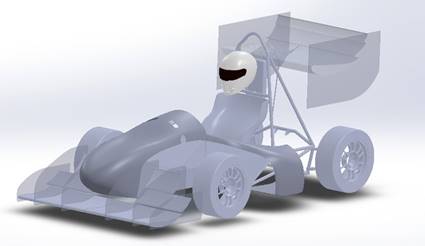
improve air flow to the cooling system and intercooler. These are presented in Fig. 1.
|
Fig.
1. View of car WT-02 with aerodynamical system |
4. PROJECT OF THE
AERODYNAMICAL SYSTEM
Angle
of attack α is
an angle between the chord line of an airfoil and the direction of the fluid
stream. According to literature, the lift coefficient CL increases
with increase of α.
The peak for CL is obtained for α = 10÷15°. Three
airflow simulations were performed respectively for angles 5°, 10°,
15° and for each one of them, pressure and velocity contours were received,
which are presented in Fig. 2-4. The simulation was made for the bottom airfoil
of the rear wing.
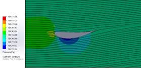
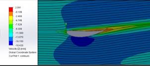
Fig.
2. Pressure and velocity contours for α = 5°
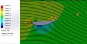
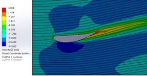
Fig.
3. Pressure and velocity contours for α = 10°
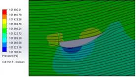
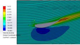
Fig.
4. Pressure and velocity contours for α = 15°
It
follows from the above that for angles 10° and 15° under- and
overpressure zones are located in similar places relative to the surface of the
airfoil and the pressure values are comparable. For 5° angle of attack, the
airfoil produces comparable underpressure to other settings but an explicit
overpressure zone is not created, therefore, this is not the most favourable
setting for a single element wing. However, the rear aerodynamic package is a
three-element wing, hence, for better cooperation between airfoils arnd for
guiding a part of the flow to the diffuser, the 5° angle of attack was
applied. The analysis for the rear wing is presented later.
Front
aerodynamic package consists of three airfoils, which are of various sizes and
inclination. The front wing design, in order to generate maximum downforce,
requires utilisation of utmost area, which is indirectly restricted by FSAE
rules. Applied arrangement and sizes of each airfoil are the results of
observations of similar constructions and many time-consuming airflow
simulations.
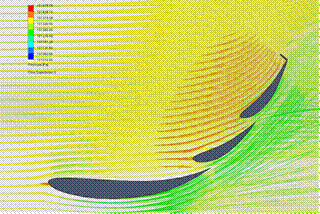
Fig.
5. Pressure contour for front wing package
From
Fig. 5, it follows that the greatest overpressure is generated over two most
leaning airfoils. The underpressure zone which is forming over the bottom
airfoil is unfavourable (this is the result of low angle of attack) but due to
this setting, a part of airflow is guided beyond the wing (in direction to the
diffuser) and also attached flow is obtained, which accumulates underpressure
underneath the wing. The stationary flap on the upper airfoil cumulates
overpressure above the wing that results in increasing downforce while
maintaining the size of the wing.
Rear
aerodynamic package, as well as front package, contains three airfoils at
various sizes and inclination. For the same reason as before, the bottom
airfoil has a low angle of attack (0°). However, the rear wing is greater
than the front wing because it is less spatially restricted and higher
downforce is preferred on the drive axle.
Fig.
6 presents the simulation of airflow for both wings assembled to the vehicle.
The streams from the front wing are directed on the way to the rear wing to
increase its efficiency.
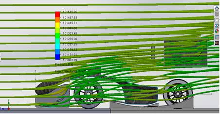
Fig.
6. Vehicle flow simulation
The
total downforce deriving from the front and rear wing were calculated.
Downforce is a function of vehicle (airflow) velocity and it increases exponentially.
WT-02 car can maximally reach around 690 N of downforce at 100 kph. The D(v)
graph is presented in Fig. 7.
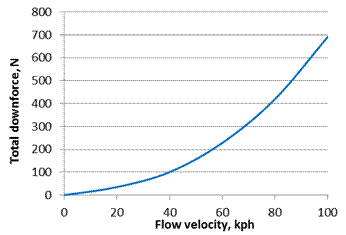
Fig. 7. Downforce vs. flow velocity
5. CONCLUSIONS
The
study simulations of airflows provided significant information about the influence
of airfoils shape and inclination to total achievable downforce. This research
leads to the following conclusions:
1. The increase in
inclination of a single airfoil affects in increasing downforce but it has to
be considered under the cooperation between airfoils on the wing, which is a
major issue.
2. To achieve greater
amounts of downforce, an aero package should be designed simultaneously with
the frame. In the discussed car, this was not done and there was no reasonable
possibility to assembly a diffuser.
3. Even though the aero
package was designed after constricting the vehicle, 150-200 N of downforce was
achieved in Endurance average speeds, which does not stand out from other
Formula Student vehicles performance.
It
seems reasonable to continue the research for the optimisation of the aero
package designand to perform tests on models in wind tunnel.
References
1.
Piechna J. 2000. Podstawy
aerodynamiki pojazdów. [In Polish: Fundamentals of vehicle aerodynamics]. Warsaw: WKiŁ.
2. Moffat J., W. Gater. 2016. Introduction to aerodynamics. School of
Engineering Blackpool and the Fylde Collage.
3. Fuller J., M. Best, N.
Garret, M. Passmore. 2013. “The importance of unsteady aerodynamics to
road vehicle dynamics”. Journal of
Wind Engineering and industrial Aerodynamics 117: 1-10.
4. Kshirsagar V., J.V.
Chopade. 2018. “Aerdynamics of High Performance Vehicles”. International Research Journal of
Engenineering and technology (IRJET) 05(03):
2182-2186.
5. Katz Joseph. 1995. Race car aerodynamics: designing for speed.
Cambridge: Bentley Publishers. ISBN: 978-0837601427.
6. 2017-18 Formula SAE Rules. SAE Interantional. 2016.
7. Milliken William F.,
Douglas L. Milliken. 1995. Race car
vehicle dynamics. SAE International. Warrendale. ISBN: 978-1-56091-526-3.
8. Kurowski Paul. 2013. Engineering Analysis with
SolidWorks Simulation 2013.
SDC Publlications. Mission. ISBN: 978-1-58503-784-1.
9. SOLIDWORKS Education
Edition - Fundamentals of 3D Design and Simulation. Dassault Systèmes SolidWorks
Corporation. Waltham. 2016.
Received 03.09.2020; accepted in revised form 03.11.2020
![]()
Scientific
Journal of Silesian University of Technology. Series Transport is licensed
under a Creative Commons Attribution 4.0 International License