Article
citation information:
Blatnický, M., Dižo,
J., Barta, D., Rybicka, I. Engineering design of a manipulator for mounting an
air suspension compressor to a car chassis. Scientific
Journal of Silesian University of Technology. Series Transport. 2020, 109, 05-16. ISSN: 0209-3324. DOI: https://doi.org/10.20858/sjsutst.2020.109.1.
Miroslav BLATNICKÝ[1],
Ján DIŽO[2],
Dalibor BARTA[3], Iwona RYBICKA[4]
ENGINEERING
DESIGN OF A MANIPULATOR FOR MOUNTING AN AIR SUSPENSION COMPRESSOR TO A CAR
CHASSIS
Summary. This article is aimed
at the engineering design of a manipulator, which is pneumatically controlled.
It will serve for mounting the compressor of an air suspension system to the
chassis of a sport utility vehicle (SUV) produced in the Slovak Republic.
The manipulator will be used on an assembly line, on which SUVs are assembled.
The designed device belongs to a group of dedicated devices, which are not
produced within a serial production, however, it is the only functional
prototype. Together with the manipulator structure, a pneumatic part of
the assembly line including individual components, schemes and the
pneumatic system will be proposed. Within the project process, all necessary
customer demands, technical and safety standards have to be met. Moreover,
ergonomic requirements for handling the device and other acts on the workplace
have to be considered.
Keywords: compressor, an air suspension system, a
chassis, engineering design, manipulation
1. INTRODUCTION
Pneumatically controlled mechanisms
are mechanisms that use the pressure force change for the incurrence of a
rectilinear or rotational movement. Pneumatic components are used in such
fields, where very high pressures are not required in comparison with hydraulic
systems. Due to clean operation, high speeds, automatisation possibilities as
well as fire safety, pneumatic systems are used in food processing, optics,
production lines, building industry and also in the automotive industry.
Further factors with which they are associated working conditions are not
included in this project [1, 4-8].
The authors assume that the
designed device will make human labour easier and make the car production
process more effective. The main requirement consists in mounting the
compressor of an air suspension system of a car [11-14] from beneath the
chassis, specifically, from the right rear part of the car. For other
requirements to be considered, we include [2, 3]:
- the manipulator
structure has to respect the mechanical actuation of the device and the weight
of the mounted component,
- the manipulator
structure, type and location of control elements have to be chosen with respect
to the device operating staff, that is, the device has to be controlled by just
one operator,
- compactness,
stiffness and the minimal weight of the manipulator,
- the air
compressor has to be attached on the manipulator arm without clamps,
- guaranteed the
possibility of the subassembly of the compressor on the manipulator arm,
- reliable
fixation of the manipulator to the chassis without damage,
- a longitudinal
rail system equipped with three sensors (optical, acoustic and shut),
- the manipulator
has to be equipped with sensors of medium consumption (compressed air and
electric energy),
- reliable
mounting of the compressor to the chassis, that is, the guidance of the mounted
component by the manipulator towards the chassis,
- guaranteed
access to screw connections during the process of assembling,
- an adjustable
frame of a compressor on the manipulator arm,
- the fastened
arm of the manipulator, that is, braked in extreme positions,
- simple
maintenance,
- any metal
component of a compressor support must not be in a contact with a mounted
component or the car.
2. THE ENGINEERING DESIGN OF THE
DEVICE
The engineering design
of the manipulator goes out from a scheme of the workplace with input
geometrical parameters of the workplace (Fig. 1 left). Fig. 1 left shows
the particular part of the car chassis (blue), which is placed in the position
corresponding the real position of the car chassis on the given assembly line.
The car chassis includes the compressor, which is located in the mounted
position (Fig. 1 right, yellow). This part of Fig. 1 also contains
the RPS (reference point system) point, which is the point of reference for
individual parts of the structure (Fig. 1 right, red). The chassis
has to be located in this part of the assembly line in the particular tolerance
limits. The compressor is attached in its setting without any clamps.
Dimensional definiteness
was another important demand for the accurate position of the compressor. The
compressor setting is made of PE 1000 polyethylene (Fig. 2, green).
This material is suitable for the purpose due to its high wearing quality and
resistance to abrasion. These properties are very important for the compressor
setting because almost every 90 s the compressor is put into it.
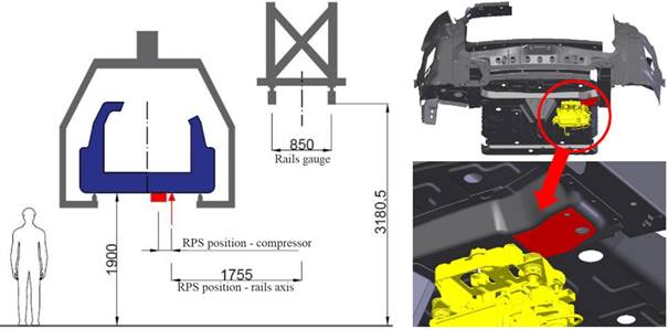
Fig. 1. Scheme of the workplace
including input data (left), a three-dimensional model of the particular
part of the car chassis (right), the specific position of the compressor
(yellow), the specific position of the RPS point (red)
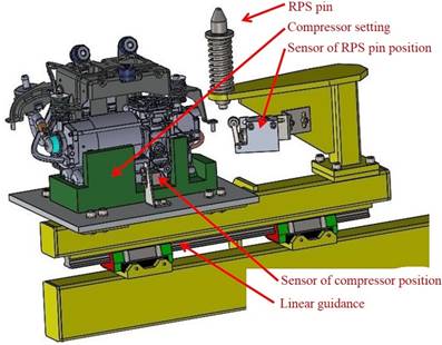
Fig. 2. The setting of
the compressor (green), RPS pin
The polyethylene setting
is placed on an aluminium plate, which is mounted on a moving beam
(Fig. 2). The aluminium plate is connected with the manipulator by means
of screw connection and slots. Slots serve for adjustment of the compressor
setting to the accurate position towards the RPS pin in x and y directions. The
aluminium plate includes also a sensor of the compressor position Festo R3-M5.
On the beam, a console with a suspended RPS pin and a sensor of the position is
placed.
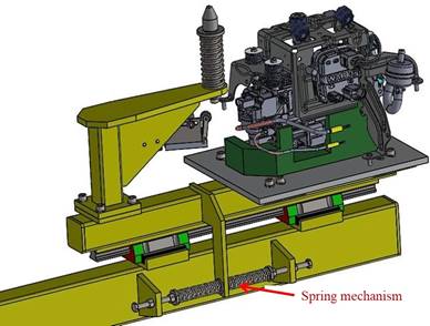
Fig. 3. A view of a spring
mechanism for centring of the compressor setting
The whole compressor
setting is movable so as to compensate of tolerances in the Y direction. It is ensured by means of a
linear guidance Hiwin HGW25HC. Decisive parameters include the static carrying
capacity. The manufacturer guarantees the static carrying capacity of
76000 N. Although, this loads will never be reached, because just the own
weight of the compressor setting and the compressor is considered and it is of
14.8 kg.
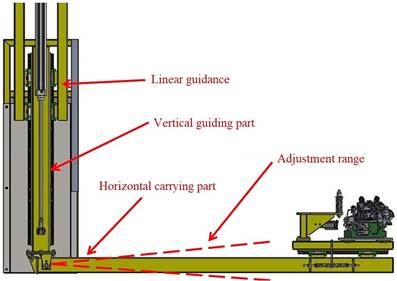
Fig. 4. A movable arm of the
manipulator
A guiding rail is
located on the compressor setting beam, other two trolleys are mounted on the
manipulator arm. Setting centring is solved by means of an adjustable spring
mechanism (Fig. 3), which keeps the setting of the tolerance zone of the
RPS pin. Adjusting of the initial position of the compressor setting before the
operation of the manipulator is ensured with screws and spring backstops.
The manipulator arm lifts the
compressor in the z-direction and it consists of two parts, specifically, a
vertical guiding part and a horizontal carrier part (Fig. 4). These parts
are connected by a connecting pin. Such a connection allows adjusting the
horizontal carrier part to the proper position by rotating around the x-axis. Adjustment is allowed by two
adjusting screws SGTPP8-40 (Fig. 5).
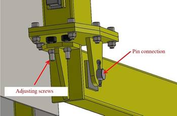
Fig. 5. An adjusting mechanism with
a pin connection
Trolleys of the linear
guidance of the compressor setting and the RPS pin are mounted on the
horizontal arm by means of shaped surfaces with defined geometry and
tolerances.
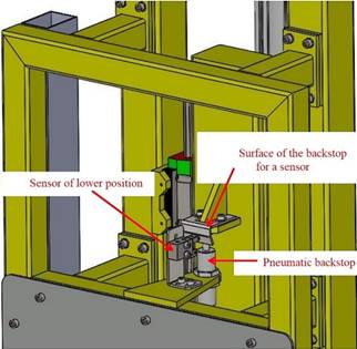
Fig. 6. A backstop of
the lower position
The vertical guiding
part of the arm consists of a rectangular profile, on which rails of the linear
guidance Hiwin HGW25HC by precision machined surfaces are placed. Two other
components are placed in the lower part: a weldment of the pin connection and a
surface for adjusting screws heads and a hole for a piston rod eye of a
pneumatic cylinder, which serves for lifting the component.
The upper part includes
the surface of the backstop for the pneumatic sensor of the upper position
Festo R3-M5. This surface comes in contact with the pneumatic backstop Festo
YSR-16-20-C. This backstop has mainly a safety function because it is the only
one mechanical element, which prevents the whole arm from sliding out of the
guidance, for example, in case of mounting or changing of the pneumatic
cylinder.
A rotating part
(Fig. 7) of the manipulator consists of two vertical profiles between
which the arm moves in the z-axis. Linear guiding trolleys are mounted on these
profile same as on the horizontal part of the arm. Both profiles are attached
to the plate, which is connected with one part of the radial-axial bearing. It
is Hiwin CRBE0925C bearing. The static carrying capacity of the bearing in the
radial direction of 80.2 kN and in the axial direction of 182 kN. The
estimated weight of the manipulator is 200 kg, it means, the proposed bearing
meets the safety criteria. The proposed bearing has to allow convenient
maintenance access.
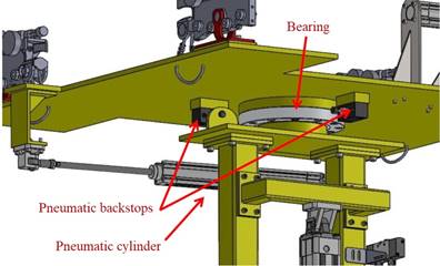
Fig. 7. A rotating mechanism
The original customer
requirement has defined manual rotating of the mechanism around the y-axis.
However, the arm must be in extreme positions fixed and manual control would
require another additional mechanism. Therefore, the rotating motion of the
mechanism is controlled by means of a pneumatic cylinder. Such a solution
allows to set the extreme positions of the rotation as well as insures the arm
in these positions. Last but not least, the operation of the operator is
facilitated. Implementation of the hydraulic arm requires to weld two surfaces
for pneumatic backstops Festo SCK-00-003. Screw character of backstops adjustment
enables precisely to determine the extreme positions of the manipulator.
Furthermore, pneumatic cylinders of lifting and rotating, an air treatment
unit, a pneumatic valve, pneumatic flexible tubes, electric cable and well as a
control panel are placed on the rotating part of the manipulator.
The control panel has to
meet technical, safety and ergonomic demands [9, 10]. As the panel is located
close to the moving part of the manipulator, any contact with this part should
be avoided (Fig. 8). A steel covering is used for this. Two-handed
operation is the other safety element. It excludes any contact of an upper limb
with the rotating part. Two-handed operation of the manipulator is solved by
means of two handles, which at the same time serve for manipulation in the x-direction and from which buttons are
operated in according to ergonomic principles.
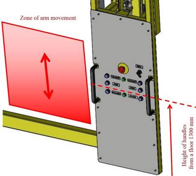
Fig. 8. The control panel with the
arm movement zone
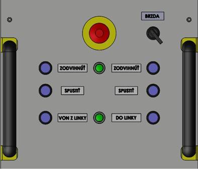
Fig. 9. The control panel
The
steel covering serves for mounting all control and display elements. It meets
requirements for simple access and manipulation within maintenance
interventions. The control panel (Fig. 9) includes seven pneumatic
buttons, two pneumatic pilot light and electric button for an emergency stop.
Pneumatic
buttons are doubled due to two-handed control, two separate buttons serve for
rotating the manipulator around z-axis and a pneumatic switch button ensures
the manipulator against movement. Moreover, pneumatic pilot lights of placement
accuracy of the compressor and the lower position of the manipulator are also
located in the operator’s field of vision. The emergency stop button is placed in the middle of
the control panel. It should be noted, that the emergency stop button is the
only one electric element on the whole manipulator structure and is powered by
voltage of 12 V.
The rear covering
protects all pneumatic and electric elements of the manipulator from contact
with the moving arm. Pneumatic flexible tubes are routed through plastic
canals.
The weight of the entire
manipulator has to be carried and moved in the x-axis direction. This is ensured by means of the trolley
(Fig. 10), which consists of a steel plate. On this plate, four trolleys
carrying and guiding the whole manipulator are mounted.
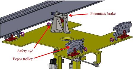
Fig. 10. The manipulator trolley
with a pneumatic brake
Trolleys are placed on
aluminium profiles Eepos L. Two profiles are able to transmit the weight of
1200 kg. These profiles are added by trolleys AL300/300. They can be
loaded in vertical direction bi-directionally by the load of 3000 N.
Trolleys are fixed to the steel plate by means of an eye, type 0˚
Standard. It can be also loaded bi-directionally by the load of 600 N. In
terms of safety, it is necessary to consider eventual damage of the trolley and
resulting potential fall of the manipulator. For this reason, every trolley
includes safety cables, which one end is located on the aluminium profile and
the other end is fixed on the manipulator.
The upper part of the trolley
contains the parking brake formed by a small pneumatic cylinder with a rubber
ending at the end of the piston rod. This rod comes in contact with the Eepos
aluminium profile in case of the parking brake activation and it prevents the
manipulator movement.
Based on technical
demands, only the lift of the arm in the z-direction
has to be pneumatically controlled. The technical assignment, as well as the
principle of function of the manipulator, requires that the arm has to be fixed
in extreme positions during rotating around the z-axis. In addition, the
manipulator has to be prevented against the movement as a whole as well as its
components, for example, in case of leaving the workplace, maintenance, etc. In
an effort to avoid unnecessarily complicated solutions, for example, using
cable, pins or others mechanisms, which would be potential sources of failures,
the pneumatic control system of rotating and braking the mechanism was chosen.
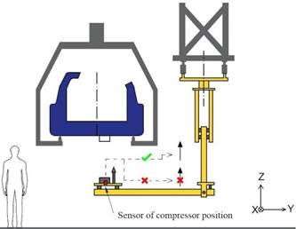
Fig. 11. A scheme of the function
of the compressor position pneumatic sensor
The pneumatic system of the
manipulator includes three pneumatic cylinders as follows:
-
the cylinder for arm lifting - DSBC-50-800-PA-N3,
-
the cylinder for rotating around the z-axis - DSBC-32-250-PA-N3,
-
the cylinder for braking in the x-axis - DSBC-32-25-PA-N3.
Pneumatic cylinders for lifting and
rotating are connected with corresponding parts of the manipulator by means of
components of Festo producer. For the pneumatic cylinder used for braking
steel, consoles are designed. To limit the manipulator’s movements to the
necessary operations, it was needed to place additional pneumatic components as
follows:
- a
sensor of a compressor position, Festo R3-M5. This sensor serves for evaluation
of the proper placing of the compressor to the setting. If the compressor is in
the proper position, the control panel shows by means of the green pneumatic
pilot light Festo OH-22-BL, the correctness of placing. The sensor also serves
as a lift condition of the arm lifting from the lower position to the upper
position and thus, it prevents to lift the arm either when no compressor is
placed on it or the compressor is placed improperly (Fig. 11).
- a
sensor in an RPS pin position, Festo RO-3-1/4-B. This sensor serves for
evaluation of proper and sufficient insertion of the RPS pin into the car
chassis. When the proper mounting position is reached, it prevents further
lifting of the arm, which could cause the lifting of the car chassis or some
other damage (Fig. 12).
- a
sensor of an arm lower position, Festo R3-M5. The main task of this sensor is
to limit the manipulator rotating with the lifted arm because in case of such
manipulation, the risk of contact of the arm with any parts of the chassis
arises. Therefore, rotating around the z-axis
is possible, when the arm is in the lower position. Similarly, reaching of this
position is indicated on the control panel by the green colour of the pneumatic
indicator Festo OH-22-BL. Another very important task of this sensor is the
prevention of activation of the brake in lifted or even mounting position, when
the manipulator, the chassis or other part could be damaged (Fig. 13).
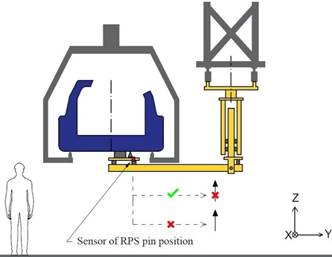
Fig. 12. Scheme of the
functionality of the RPS pin position sensor
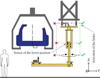
Fig. 13. Scheme of the functionality
of the lower position sensor
3. CONCLUSION
The solution of the
presented problem has consisted of obtaining input data from a customer.
Based on these data, the engineering design and functional solution of
the manipulator were created. The important task was the design of the
compressor setting, which had to meet all requirements in term of its
dimensions and the possibility of compensation of all inaccuracies. Safety of
the device, protection of health and operator and ergonomic parameters was
other important aspects of the design. Compliance with the relevant
standards and internal regulations of the customer was a matter of course.
Designs of the rotating part of the manipulator, the control panel, the travel
and the pneumatic parts of the manipulator were realised together with the
compliance of the customer-required components from precisely specified
manufacturers. The next step in solving this problem will be the design of
the pneumatic brake, the selection of air treatment equipment,
the creation of the pneumatic circuit diagram, the FEM simulation of the
steel plate, the adjustment mechanism and the RPS pin console.
Source of funding
This work was supported by the Cultural and Educational Grant Agency
of the Ministry of Education of the Slovak Republic in the project No. KEGA
023ŽU-4/2020: Development of advanced virtual models for studying and
investigation of transport means operation characteristics.
References
1.
Benevičius
V., V. Ostaševičius, R. Gaidys. 2013. „Human body rheology
impact on measurements in accelerometer applications”. Mechanika 1: 40-45.
2.
Corejova
Tatiana, Emilia Imriskova. 2008. “Convergence at the Postal
Market”. Eksploatacja i
Niezawodnosc-Maintenance and Reliability 1(3): 74-76.
3.
Droździel
Paweł. 2008. “The influence of the vehicle work organization
conditions on the engine start-up parameters”. Eksploatacja i Niezawodnosc - Maintenance and Reliability 1(3):
72-74.
4.
Droździel
Pawel, Kamil Wawer, Radovan Madleňák, Murat Omarbekovich
Mussabekov. 2017. “Concepts of load handling devices, adjusted to light
goods vehicles of the weight up to 3.5t”. Communication – Scientific Letters of the University of Zilina
19 (2): 96-102. ISSN: 1335-4205.
5.
Gerlici
Juraj, Iryna Shvedchykove, Inna Melkonova, Julia Romanchenko. 2017.
“Investigation of influence of separator magnetic system configuration
with permanent magnets on magnetic field distribution in working area.” Electrical Engineering & Electromechanics 2: 13-17. ISSN: 2074-272X.
6.
Liščák
Štefan, Paweł Droździel. 2006. “The chosen problem of
urban and suburban transportation”. Eksploatacja i Niezawodność 1. Polskie Naukowo-Techniczne Towarzystwo
Eksploatacyjne. PAN O/Lublin. P. 54-58.
7.
Madlenakova
Lucia, Mária Matuskova, et al. 2016. “Intermodal Transport
Terminals as Part of the Postal Transportation Network”. Transport Means 2016. 20th Intern.
Scientific Conference, Kaunas University of Technology. ISSN: 1822-296 X.
P. 556-561.
8.
Ostasevicius V.,
V. Jurenas, A. Juskevicius. 2014. „Modified tool structures for effective
cutting”. Mechanika 2: 171-176.
9.
Papacharalampopoulos
Alexios, Aivaliotis Panagiotis, Makris Sotiris. 2018. “Simulating robotic
manipulation of cabling and interaction with surroundings”. International Journal of Advanced
Manufacturing Technology 96 (5-8): 2183-2193. ISSN: 1433-3015. DOI:
10.1007/s00170-018-1675-9.
10.
Parmová
J., L. Urban. 2008. “Ergonomic intervention at the assembly line of the
Skoda Roomster car”. Ceske Pracovni
Lekarstvi 9(4): 121-124. ISSN: 1212-6721.
11.
Stańczyk
Marcin, Tomasz Figlus. 2014. „The influence of the hardening coolant
agent on the properties of hot rolled bars of the steel 42CrMo4”. Metalurgija 53(4): 493-496. ISSN:
0543-5846.
12.
Figlus
Tomasz, Łukasz Kuczynski. 2018. „Selection of a semi-trailer for the
haulage of long oversize loads, taking into account an analysis of operational
damage". XI International
Science-Technical Conference Automotive Safety. IEEE. DOI:
10.1109/AUTOSAFE.2018.8373342.
13.
Shalabi
Mohamed Essam, Haitham El-Hussieny, Ahmed Ali Abouelsoud, Ahmed M.R. Fath
Elbab. 2019.”Control of automotive air-spring suspension system using
Z-number based fuzzy system”. IEEE
International Conference on Robotics and Biomimetics “ROBIO 2019”:
1306-1311. Dali, China. 6-8 December 2019, Dali, China.
14.
Tan
Xiaoyan, Jiansheng Hu, Guisheng Dong, Bo Chen. 2019. “An electronic
control air suspension system for commercial vehicles”. IOP Conference Series: Earth and
Environmental Science 267(4). E-ISSN: 1755-1315.
Received 23.08.2020; accepted in revised form 02.11.2020
![]()
Scientific
Journal of Silesian University of Technology. Series Transport is licensed
under a Creative Commons Attribution 4.0 International License