Article
citation information:
Drbal, M. A method of rotary engine
performance prediction. Scientific
Journal of Silesian University of Technology. Series Transport. 2020, 108, 37-43. ISSN: 0209-3324. DOI: https://doi.org/10.20858/sjsutst.2020.108.4.
Milan DRBAL[1]
A
METHOD OF ROTARY ENGINE PERFORMANCE PREDICTION
Summary. The rotary engine mainly developed for the
automotive industry by the NSU corporation is currently used in unmanned
aircraft, transportable generators and small watercraft. In the early stage of
the engine development, the simulation of the performance characteristics is
advisable. The 3D CFD engine simulation is highly expensive in terms of CPU
time demand and requires a high level of optimisation to provide adequate data.
This method can be used later in the development and fine engine tuning. For
the design of the prototype 1D, simulation is being used as a tool to compare
various designs of the engine. While the current commercially available
software (GT-suite, Ricardo Wave, etc.) is being improved marginally, the
functionality of the software is being tested on the piston reciprocating
engines. This paper explores the possibility of the algorithms of such a
software to be used on the rotary engine thermodynamic simulation and provides
an approach to design a simulation model that can be solved by the software to
predict the performance characteristics of the engine prototype.
Keywords: internal combustion engine, rotary engine, 1D
simulation
1. INTRODUCTION
The commercially available performance
prediction software (GT-power, Ricardo Wave, etc.) for combustion engines
currently does not include support for rotary engines. The main reason is the
significantly lower market demand for these engines. For the time-efficient
prediction of the performance parameters during the early stage of the
development of the rotary power unit, it is advisable to use a one –
dimensional software. Unfortunately, the direct use of the available software
for the piston engines is not possible because of the following differences
between the two engine designs [3, 16-18, 21, 23, 24, 26]:
- the ratio of the main shaft rotation to the
4-stroke cycles of the rotary engine is equal to 3. Single-cylinder 4-stroke
piston engine crankshaft rotates twice for the same quantity of cycles,
- the difference of the surface to displacement
ratio during the main-shaft rotation,
- the difference in the heat-transfer proprieties
coming from the differences in the geometric shape of the combustion chamber,
- the length of the combustion chamber increases the
time of the combustion process, which reduces the overall efficiency of the
combustion,
- the movement of the working chamber across the
whole loop of the main housing influences the difference in the temperature
distribution of the engine. The speed of this process also influences the speed
of the flame propagation through the working chamber as the leading apex seal
of the rotor is constantly moving forward from the flame front.
The main objective of this paper is the creation
of the virtual piston engine (VPE) with modified parameters that correspond to
the designed rotary engine. The VPE will then be used as a model for the 1-D
solver to provide the required data for the development process.
Responsibility for the use of photos and
drawings in the sent materials of articles rests on the authors.
2. COMPUTATIONAL MODEL
The initial condition in the
simulation model setup must be the equity of the volume of the operating
chambers in relation to the crankshaft rotation.
As the input, the piston position of
the virtual piston engine (VPE) in relation to the crank-shaft angle α is
used in the algorithm, the equation used for the virtual piston position [14]:
![]() (1)
(1)
where e
is the eccentricity of the rotary mechanism, λ is the trochoid constant, α is the relative angle of the rotor, S4 is the area between the outer shell of the trochoid
and the line between 2 apexes of the rotor, hp
is the rotor width and Vp
is the rotor hollow volume.
The bore of the VPE is taken as the diameter of
the circle with equal area to the area of the rotor exposed to the working
chamber. The head area of the cylinder of the piston reciprocating engine
remains constant during the engine operation, however, in the rotary engine
from its principle the area changes with the main shaft rotation. This
difference is not accounted for in the algorithms for the 1D simulation solver.
The virtual area of the head equivalent surfaces is therefore calculated as the
weighted average with the heat flux to the head area as the weight of the
calculation. The rotary engine of the Wankel type works with four-stroke cycle
and each rotor and housing pair creates 3 working chambers. For these reasons,
using the four-stroke template with 3 cylinders configuration is advisable. To
maintain the equity of the volumetric flow through the VPE and the rotary
engine, the ratio of the main shaft rotation to the rotation of the crankshaft
of the VPE is 3/2. The cylinders are interconnected with the piping of the negotiable
length simulating the overflow of the exhaust and the intake during the port
openings to the adjacent chambers. Both intake and exhaust port openings were
simulated with a kinematic simulation to determine the active areas of the
ports in relation to the main shaft rotation. The calibration of the flow
coefficient of the ports was done using the CFD approach (Fig. 2), then further
calibrated in the GT-Power software via volumetric flow measured on the test
engine.
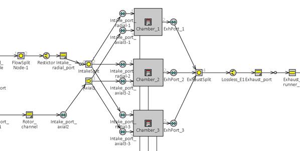
Fig. 1. Base structure of the mathematical
model
3. SIMULATION RESULTS
For
the first iteration of the port flow coefficients calculation, the 3D CFD
method was used [13]. As the experimental method of using the blow through
mass-flow measuring station cannot be executed in the early stages of the
development due to the lack of the physical engine model, using the commercial
computational software is the only option to determine these parameters. The
discharge coefficients of the intake and exhaust system were computed at the
major points of the system. Intake and exhaust port opening and closing
discharge coefficients were approximated by the linear function as this
approach reduces the time needed for the 3D CFD method and can be used without
large error as presented in the [2]. Due to the complexity of the axial intake
system on the simulated engine, two simulations were carried out [4, 5]. The
results of the simulations were then used to calibrate the 1D model of the
virtual piston engine.
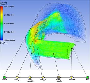
Fig. 2. Axial intake port 3D calibration
Using
the previous input data calibrations from the known engine, the simulation was
run to evaluate the concept of the virtual piston engine creation. For the
engine performance, the average difference of the simulated and measured values
was 3.08% (Fig. 3). Torque and power are the overall engine characteristics,
which determine the quality of the method used in the simulation, however, for
the previously mentioned discharge coefficient calibration validation of the 1D
model, engine air mass flow is used.
Fig. 3. Engine prediction
correlation with measured data
4. CONCLUSION
As the commercially available software for
thermodynamic simulation of the rotary engine is not available due to the
comparably low market demand to the reciprocating-piston engine type, the
available software input can be modified to provide accurate simulation
results. The method of creating the virtual piston engine is shown using the
calculated bore, stroke and piston position data to provide the equivalent
surface area and volume of the working chamber. The calculation method using
the 3D CFD software was applied for the complicated axial intake of the engine.
Using the outcome of the 3D simulation, the 1D simulation model was calibrated
to provide the comparable mass air flow results. The heat transfer coefficients
were calculated using the forced convection over the flat plane analogy. These
results are then used as weight for the average calculation of the head surface
area, which remains constant in the reciprocating-piston engine but changes
with the angle of the main shaft in the rotary engine. For future work, testing
is required to measure the in-cylinder pressure data and temperature and
pressure data from the engine intake and exhaust system as these are to be used
for the model calibration. Additionally, further development of the rotary
engine needs to solve NVH problems using the methods described in [10, 11, 19, 20,
22] and further modify using prototyping methods [8, 9], the control units for
its specific applications. Using this advanced simulation and experimental
methods, the new rotary engine unit parameters can be designed, optimised and
performance predicted. Modern production technologies [1, 6, 7, 12, 15, 25]
will be used to produce optimised rotary engine components.
Acknowledgement
The authors gratefully
acknowledge funding from the Specific research on BUT FSI-S-20-6267.
References
1.
Balevicius
Gytautas, Vytautas Ostaševičius, Vytautas Jurėnas, Jolanta
Baskutienė, Robertas Zakrasas. 2016. „Investigation of vibration
assisted drilling prospects for improving machining characteristics of hard to
machine materials at high and low frequency ranges”. Mechanika 2: 125-131.
2.
Bartrand Timothy
A., Edward A. Willis. 1990. „Performance of a supercharged
direct-injection stratified-charge rotary combustion engine”. Symposium General Aviation Systems:
1-24. Cosponsored by the AIAA and FAA
National Aeronautics and Space Administration, Cleveland, USA. 11-12 April
1990, Ocean City, USA.
3.
Brestovič
Tomáš, Natalia Jasminská, Mária
Čarnogurská, Michal Puškár, Michal, Kelemen Milan
Fiľo. 2014. „Measuring of thermal characteristics for Peltier
thermopile using calorimetric method”. Measurement 53: 40-48. DOI: https://doi.org/10.1016/j.measurement.2014.03.021.
4.
Handschuh Robert
F., Owen Karl A. 2010. Analysis of apex
seal friction power loss in rotary engines. Cleveland: Glenn Research
Center.
5.
Irion C.E., R.E.
Mount. 1992. Stratified charge rotary
engine critical technology enablement. Volume I. Wood-Ridge: Lewis Research
Center.
6.
Karpavičius
Paulius, Vytautas Ostaševičius, Vytautas Jūrėnas, Jolantas
Baskutienė. 2017. „Self-powered wireless sensor system application
for cutting process control”. Mechanika
23(3): 456-461.
7.
Košinár
Matúš, Ivan Kuric. 2011. „Monitoring possibilities of CNC
machin tools accuracy”. 1st
International Conference on Quality and Innovation in Engineering and
Management (QIEM): 115-118. Cluj
Napoca. 17-19 March 2011. ISBN: 978-973-662-614-2.
8.
Kučera Pavel,
Václav Píštěk. 2019. „Prototyping a system for
truck differential lock control”. Sensors
19(16): 1-18. ISSN: 1424-8220. DOI: 10.3390/s19163619.
9.
Kučera Pavel,
Václav Píštěk. 2017. „Testing of the mechatronic
robotic system of the differential lock control on a truck”. International Journal of Advanced Robotic Systems
14(5): 1-7. ISSN: 1729-8814. DOI: 10.1177/1729881417736897.
10. Kučera Pavel, Václav
Píštěk. 2017. „Truck vibrations caused by rotating shaft
deflection”. Journal of
Vibroengineering 19(7): 5361-5373. ISSN: 1392-8716. DOI:
10.21595/jve.2017.18028.
11. Kučera Pavel, Václav
Píštěk, Aleš Prokop, Kamil Řehák. 2018.
„Measurement of the powertrain torque”. 24th International conference Engineering Mechanics: 449-452.
Institute of Theoretical and Applied Mechanics of the Czech Academy of
Sciences, Prague, Czech Republic. 14-17 May 2018, Svratka, Czech Republic.
ISBN: 978-80-86246-88-8.
12. Kuric Ivan. 2011 „New methods and trends in
product development and planning”. 1st
International Conference on Quality and Innovation in Engineering and
Management (QIEM): 453-456. Cluj Napoca, 17-19 March, ISBN:
978-973-662-614-2.
13. Neumann Stefan, Roman Varbanets, Olena Kyrylash,
Oleksiy Valerievich Yeryganov, Vladyslav Olegovich Maulevych. 2019.
“Marine diesels working cycle monitoring on the base of IMES GmbH
pressure sensors data”. Diagnostyka
20(2): 19-26. DOI: https://doi.org/10.29354/diag/104516.
14. Norbye Jan P. 1971. The Wankel engine: design, development, applications. Denver:
Chilton Book Co. ISBN: 0801955912.
15. Ostasevicius V., V. Jurenas, A. Juskevicius. 2014.
„Modified tool structures for effective cutting”. Mechanika 2: 171-176.
16. Pacana A., K. Czerwińska, L. Bednarova. 2019.
“Comprehensive improvement of the surface quality of the diesel engine
piston”. Metalurgija 58(3-4): 329-332. ISSN: 0543-5846.
17. Pacana A., K. Czerwińska, L. Bednarova. 2018.
“Discrepancies analysis of casts of diesel engine piston”. Metalurgija 57(4): 324-326. ISSN: 0543-5846.
18. Piątkowski J. 2015. “AlSi17Cu5Mg alloy as
future material for castings of pistons for internal combustion engines”.
Metalurgija 54(3): 511-514. ISSN: 0543-5846.
19. Píštěk Václav, Lubomír
Klimeš, Tomáš Mauder, Pavel Kučera. „Optimal design
of structure in rheological models: an automotive application to dampers with
high viscosity silicone fluids”. Journal
of Vibroengineering 19(6): 4459-4470. ISSN: 1392-8716. DOI:
10.21595/jve.2017.18348.
20. Prokop Aleš, Barbora Kopečková, Kamil
Řehák. 2017. „Gear drive system simulation of input
parameters effect on rattle”. 14th
Conference Acoustics and Vibration of Mechanical Structures (AVMS):
381-388. University Politehnica Timişoara, Timişoara, Romania. 25-26
May 2017, Timisoara, Romania. ISBN: 978-3-319-69822-9.
21. Puškár Michal, Tomáš
Brestovič, Natalia Jasminská. 2015. „Numerical simulation and
experimental analysis of acoustic wave influences on brake mean effective
pressure in thrust-ejector inlet pipe of combustion engine”. International Journal of Vehicle Design 67(1):
63. DOI: https://doi.org/ 10.1504/ijvd.2015.066479.
22. Řehák Kamil, Pavel Kučera, Aleš
Prokop. 2019. „Application of virtual prototype to heavy-duty gearbox
housing evaluation”. International
Scientific Conference Transbaltica XI: Transportation Science and Technology:
361-368. Vilnius Gediminas Technical University, Vilnius, Lithuania. 2-3 May
2019, Vilnius, Lithuania. ISBN: 978-3-030-38665-8.
23. Sinay Juraj, Michal Puškár, Melichar
Kopas. 2018. „Reduction of the NOx emissions in vehicle diesel engine in
order to fulfill future rules concerning emissions released into air”. Science of the Total Environment 624:
1421-1428. DOI: https://doi.org/10.1016/j.scitotenv.2017.12.266.
24. Tartakovsky Leonid, Vladimir Baibikov, Marcel Gutman,
Mark Veinblat M. 2012. ,,Simulation of wankel engine performance using
commercial software for piston engines”. SAE Technical Paper 32 0098: 1-13. ISSN: 0148-7191. DOI:
10.4271/2012-32-0098.
25. Tlach Vladimír, Miroslav Císar, Ivan
Kuric, Ivan Zajačko. 2017. „Determination of the industrial robot
positioning performance”. MATEC Web
of Conferences 137(01004). DOI: https://doi.org/
10.1051/matecconf/201713701004.
26. Todić V, J. Tepić, M. Milošević,
D. Lukić, M. Hadžistević. 2012. “Design of casting blanks
in CAPP system for parts of piston-cylinder assembly of internal combustion
engines”. Metalurgija 51(1): 75-78. ISSN: 0543-5846.
Received 07.04.2020; accepted in revised form 20.06.2020
![]()
Scientific
Journal of Silesian University of Technology. Series Transport is licensed
under a Creative Commons Attribution 4.0 International License