Article
citation information:
Andrearczyk, A., Bagiński, P. Vibration analysis of a
turbocharger with an additively manufactured compressor wheel. Scientific Journal of Silesian University of
Technology. Series Transport. 2020, 107,
05-17. ISSN: 0209-3324. DOI: https://doi.org/10.20858/sjsutst.2020.107.1.
Artur
ANDREARCZYK[1], Paweł BAGIŃSKI[2]
VIBRATION
ANALYSIS OF A TURBOCHARGER WITH AN ADDITIVELY MANUFACTURED COMPRESSOR
WHEEL
Summary. This article presents the vibration analysis of a
turbocharger, whose compression wheel was manufactured using a high-precision
additive manufacturing technology. Currently, there are advance studies around
the world for the development of parts of innovative fluid-flow machines using
additive manufacturing techniques. The experimental research was carried out
under conditions of reduced flow temperatures. The tests and the analysis were
performed on a wheel manufactured using a 3D printing technology and on a
conventionally used aluminium wheel. Apart from an FFT analysis of the
vibration signal during machine operation, a machine run-up test was conducted
(up to a speed of 105,000 rpm). The results showed the positive impact of the
use of a plastic wheel on the dynamics of the system at a certain speed range,
which might contribute to the development of a new method to optimise the
geometry of flow systems in small high-speed turbomachines. A modified
automotive turbocharger was subjected to experiments on a test stand.
Keywords: additive manufacturing, compressor wheel, vibration
analysis, polymer
1. INTRODUCTION
The use of additive
manufacturing (AM) technology to accelerate the development of prototypical
solutions in machines and reduce their cost has been on the increase in recent
times. Presently, research on the use of 3D printers for the development of new
prototypes and the optimisation of already existing parts is being carried out.
Since AM technology is widely used and many trials conducted to implement
different materials in diverse fields of science and engineering [1, 2], a
number of studies on the physical properties of the materials used in this
technology need to be carried out. This is important as they make possible
better specification of the field of application of this technology.
Vibration analysis during
machine operation is essential in determining the dynamics of the system and is
mainly carried out for diagnostic purposes [3, 4], more so, it is performed for
the accurate identification of faults and causes of machine instability [5, 6,
7, 8, 9]. This study is based on an automotive turbocharger machine. There are
a number of articles on vibration analyses performed on these types of machines
[10, 11, 12], thus, making the determination of their technical conditions
quick and precise, revealing the reasons behind these conditions. Article [13],
based on the analysis of the vibration spectrum of a turbocharger, describes a way to measure the speed of rotation using the
signals tested. This literature review indirectly contributed to the selection
of a turbocharger as a research object.
So far, in the field of
AM technology, vibration tests have been carried out on 3D printers to improve
the quality of the elements manufactured or to speed up the printing process.
It was only in the article [14] that the vibration properties of 3D-printed
elements were investigated using the modal analysis to determine the natural
frequencies of a research object. Given that there are no studies on the
influence of the use of additively manufactured components on the dynamics of
machines, a decision was made to perform vibration analysis on a turbocharger,
whose compressor wheel was manufactured using a selected 3D printing
technology.
This article describes
the experimental tests that were carried out on a test stand used to determine
the characteristics of turbocharger compressors and presents some of the
selected results of the vibration analysis of the turbocharger with an
aluminium (original) compressor wheel and a polymer one (3D-printed), which has
been tested at high rotational speeds under various operating conditions. This
article is a continuation of research on the use of 3D printing technology in
the experimental verification of the optimised rotor discs that are mounted in
turbomachines. Previous work established that the results of flow calculations
are consistent with the experimental results obtained for aluminium and polymer
discs. The aim of this work was to compare the dynamic properties of a
conventional turbocharger when using a disc made of aluminium or polymer.
2. MANUFACTURING
TECHNOLOGY
The Institute of
Fluid-Flow Machinery, Polish Academy of Sciences (IMP PAN) uses three different
AM technologies. Based on criteria such as printing precision, printing time
and cost of mass production, the MultiJet Printing (MJP) technology used in a
printer produced by the 3D Systems Company (model HD 3500 Max) was selected.
This technology makes achieving very high printing precision (the thickness of
a single layer printed by the device is 16 µm with an accuracy of up to 1
µm) possible. The producer offers a range of materials that have
different mechanical properties. The material sold under the trade name VisiJet
M3 X in the form of a fluid polymer resin was chosen to manufacture the
compressor disc as it has the best properties. The studies carried out on its
mechanical properties showed that the tensile strength is about 54 MPa [15].
The manufacturing
process, which is based on MultiJet Printing technology, is characterised by
putting layers of material through printhead jets that are distributed over the
entire printing platform. The MJP method is based on the inkjet approach to
create 3D elements and photo-cure the printed photopolymer layers using
ultraviolet light.
However, this method
should not be used at high ambient temperatures as it may cause errors during
the printing process. MultiJet Printing is one of the most precise 3D printing
technologies; it uses piezoelectric nozzles located in a printhead to deposit
thin layers of photocurable resin and wax (support material). MJP is used to
create parts with complex shapes, that is, parts with large amounts of details
and complex geometries. The use of the support material (wax) is a huge
advantage of this method as it dissolves at a temperature of 60°C leaving
no trace on the printed element. According to the producer, the selected
building material plasticises at a low temperature (88°C).
3. RESEARCH OBJECT AND
MEASURING EQUIPMENT
As earlier mentioned, a
turbocharger was selected for the experiments. It is a machine widely used in
the automotive industry. In combustion engines, the compressor rotor supplies
additional air to the combustion chamber through the intake manifold. Nowadays,
one of the most important components of a modern engine is the turbocharger. It
is a rotating machine, which consists of a turbine and a compressor, both
mounted on a common shaft. The operating principle and main components of the
turbocharger are shown in Fig. 1. The following factors influenced the choice
of this machine: the nature of its operation (in terms of dynamics) as
documented in the literature, its high rotational speed, its construction, the
easy assembling and disassembling of the components. The machine casing is
divided into three sections, which perform different functions, even though the
machine has only one shaft. In the supply section of the machine (red colour),
there is a spiral casing that supplies exhaust to the turbine blades to set it
in motion and transmit the torque to the compressor disc via the shaft. The
central section of the machine (green colour) supply oil to the slide bearings
and the thrust bearing, necessary for their lubrication. The supercharging
section of the machine (blue colour) is for the pressure charging of the
engine. This section was chosen for experimental purposes as it is a cool
section (from the viewpoint of the operating temperature) and the rotor disc
can be easily disassembled.
The compressor disc is
the part of the turbocharger that has been manufactured using MJP technology.
The printed polymer disc and the original aluminium disc are shown in Fig. 2. A 3D
laser scanner was used to reproduce the original geometry of the aluminium disc
and a cloud of points was obtained this way, which was then used to create
a model for use in a 3D printer. The geometric dimensions of the two discs were
checked and no manufacturing inaccuracies were detected. The polymer disc has
the same dimensions as the aluminium disc and they are as follows: diameter
near the split blades – 42.5 mm, diameter near the supply of the
compressor (that is, near the non-split blades) – 30 mm. The discs used
in the experiments are shown in Fig. 2.
Conventional
turbocharger test stands use engine exhaust, as in the case of this paper [16].
Due to the properties of the material from which the tested disc was made,
particularly due to its maximum operating temperature (88°C), it was
necessary to carry out this study on the test stand at reduced supply
temperatures. Compressed air (which could be heated to a temperature
between 30°C and 150°C, respectively) was used instead of engine
exhaust.
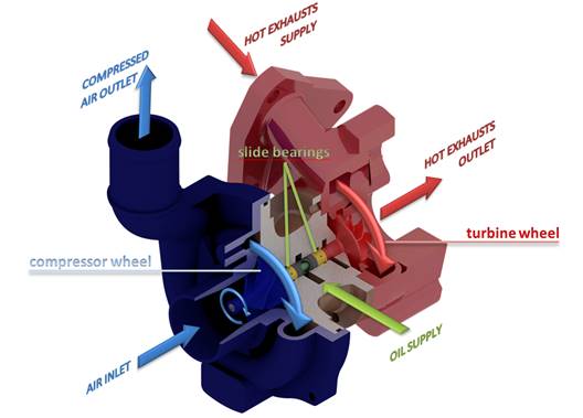
Fig. 1.
Design and operation of a turbocharger divided into three sections:
compressor section (blue colour), lubrication system (green colour)
and turbine section (red colour)
Fig. 2. Compressor wheel
manufactured using the MJP method (left)
and the original one (right)
Heating was used to
maintain the appropriate temperature at the turbine outlet. Due to the
expansion of the air, the temperature of the medium could have dropped
significantly (even below zero degrees Celsius), which could have caused damage
to the machine. The test stand [17] was equipped with all the necessary
elements such as a lubrication system, a heating system, sensors and valves
used to regulate the rotational speed of the device. Furthermore, the oil
supply pressure to the bearings has a considerable impact on the machine
vibrations. In a combustion engine, the oil pressure is regulated by the engine
speed. Since the test stand was not equipped with such a system, an oil pump
was used for this purpose, which maintained the oil pressure in the range of
2.5-4 bar (using an inverter), depending on the current speed of the
compressor. The test stand, as well as the marked sensors required to perform
measurements, are shown in Fig. 3.
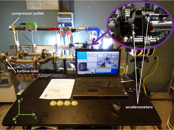
Fig. 3. Turbocharger
test stand
Vibration sensors were mounted in the X- and
Z-direction (Cartesian coordinate system shown in Fig. 3). Besides vibrations, other parameters were also
measured (such as temperatures on both sides of the turbocharger, supply
pressure and flow rate) to test the operating parameters, but were not
discussed in this paper. Accelerometers produced by the PCB Piezotronics
Company were used to measure vibrations.
4. RESULTS OF THE EXPERIMENT
The first part of the
experiment involved testing the compressor using different compressor wheels.
During the tests, a throttle valve was used to regulate the mass flow, thus, a
study of the different operating states of the machine was obtainable. The
tests were conducted with discs made of two different materials. The aluminium
disc had a mass of 16.18 g and the polymer disc, 7.26 g. First, a run-up test
of the machine was carried out with the results shown in Figs. 4 and 5,
respectively.

Fig. 4. Colourmap from run-up test conducted with aluminium compressor
wheel
(speed range: from 10,000 rpm to 105,000 rpm)
During
the run-up test performed with the aluminium disc, an increased vibration level
associated with 1X was observed at speeds above 50,000 rpm and was highest at a
speed of 105,000 rpm (Fig. 4). Vibrations associated with the operation of the
bearings (0.5X) occurred as soon as the rotational speed exceeded 70,000 rpm
and they became dominant in the vibration spectrum at higher speeds. When a
higher vibration amplitude developed (resulting from the unbalance), the 5X
component was visible (a component that was associated with the flow of
compressed air through the compressor blades,
five split blades and five non-split blades). The eigenfrequency of the test
stand, which was around 3,000 Hz, was characterised by a low vibration level
visible in the colourmap. Its harmonics and subharmonics can be noticed.
As with
the polymer disc, an increase in vibration level (1X) was observed at speeds
ranging from 35,000 to 75,000 rpm (Fig. 5). The highest vibration amplitude
occurred at a speed of 50,000 rpm (resonance zone) and was 0.5 g higher than
that in the experiment of the aluminium disc. In comparison with the aluminium
disc, component 0.5X attained a higher level of vibrations and its maximum
value was 0.8 g. The eigenfrequencies of the test stand can be seen in the
colourmap. Unlike in the previous test with the aluminium disc, the 5X
component did not appear, which could be associated with the less efficient
operation of the compressor.
To
thoroughly evaluate the dynamic performance of the tested machine, it was
necessary to perform the FFT analysis of the signals recorded at selected
rotational speeds. The results, which were obtained in the X-direction, are
shown in Figs. 6-9. They are analysed in the following part of the article.
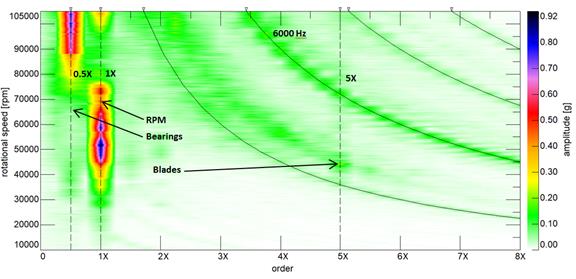
Fig. 5. Colourmap from run-up test conducted with polymeric compressor
wheel
(speed range: from 10,000 rpm to 105,000 rpm)
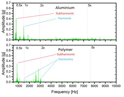
Fig. 6. Vibration amplitude spectra (in the X-direction) of the
turbocharger,
obtained at a rotational speed of 90,000 rpm for two different compressor
wheels
without throttling the flow at the compressor outlet
Fig. 6
shows frequency-amplitude graphs, for the experiments carried out with the
aluminium and polymer disc without throttling the flow at the outlet of the
compressor. In both experiments, the 0.5X component (associated with the
vibrations of slide bearings) is dominant. In the bottom graph (polymer disc),
the 1X component is about five times higher than in the top graph, however, it
can be seen that the spectral components are present within the frequency range
from 2,500 to 3,000 Hz.
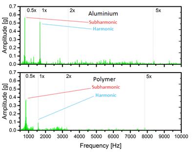
Fig. 7. Vibration amplitude spectra (in the X-direction) of the
turbocharger,
obtained at a rotational speed of 90,000 rpm for two different compressor
wheels at
a throttle level of 60%
After the flow was
throttled at the compressor outlet (Fig. 7), the vibration amplitudes of the
0.5X and 1X components approximately doubled at a speed of 90,000 rpm in the
case of the aluminium disc, while for the polymer disc, they were at the same
level. Regarding the aluminium disc, it can be similarly observed that the
component associated with the functioning of the bearings (0.48X) shifted towards
lower frequencies, indicating that an oil whirl had occurred.
Similar
vibration spectra were obtained at a speed of 100,000 rpm. Fig. 8 shows the
results of the experiment carried out without throttling the flow. As with the
aluminium disc, the vibration amplitudes increased as expected. The 0.5X and 1X
components are dominant, as it was the case at a speed of 90,000 rpm. With
regard to the polymer disc, a considerable increase in the vibration amplitude
resulting from the unbalance (1X) was observed, however, the 0.5X component
increased with an increase in the rotational speed.
During
throttling the flow at the compressor outlet, the values of amplitudes were at
a similar level at a speed of 100,000 rpm (Fig. 9) for both discs. As for the
aluminium disc, the component associated with the functioning of the bearings moved
towards the lower frequencies (to 0.4X),
indicating that the oil whip instability had occurred.
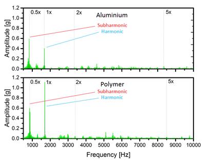
Fig. 8. Vibration amplitude spectra (in the X-direction) of the
turbocharger,
obtained at a rotational speed of 100,000 rpm for two different compressor
wheels
without throttling the flow at the compressor outlet
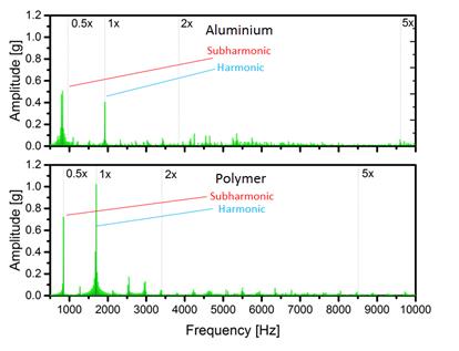
Fig. 9. Vibration amplitude spectra (in the X-direction) of the
turbocharger,
obtained at a rotational speed of 100,000 rpm for two different compressor
wheels at
a throttle level of 60%
Due to
the oil whip instability and a suspected local disruption of the airflow in the
compressor of the turbocharger (that is, the compressor stall), a decision was
made to analyse the vibration acceleration signals measured in the Z-direction.
These phenomena are often accompanied by a rise in the vibration level in this
direction. Figs. 10 and 11, respectively, show the vibration spectra which were
measured in the Z-direction during the tests of the two discs conducted under
different operating conditions.
In the
case of the aluminium disc, component 1X is dominant in the FFT
amplitude-frequency spectrum (Fig. 10) having the following values: 0.45 g
(without throttling) and 0.69 g (with throttling). The 0.5X component is
visible but its value is about half that of the 1X component. As for the
experiment conducted without throttling the flow, the 0.75X component can be
observed, which is not associated with the compressor stall. The increased
vibration amplitudes that occur at frequencies of 3,000 and 4,900 Hz are
related to the eigenfrequencies of the test stand. After the flow was throttled at the
compressor outlet, an increase in the amplitude of vibrations associated with
the 5X component was observed (blades) and, as in the case of vibrations
registered in the X-direction, the subharmonic linked to the functioning of the
bearings moved towards lower frequencies (to 0.4X), indicating that the oil
whip instability had occurred. Other components
likewise appeared (at different frequencies), which may indicate that the
compressor stall phenomenon occurred.
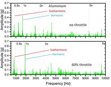
Fig. 10. Vibration amplitude spectra (in the Z-direction) of the
turbocharger, obtained at a rotational speed of 100,000 rpm for an aluminium
compressor wheel
under different operating conditions
As for
the polymer disc, after analysing the spectrum shown in Fig. 11, it was
discovered that there was no oil whip instability. However, the 0.75X component
was dominant and its value exceeded 0.5 g. During throttling, there was no
increase in the rotational speed as in the case of the aluminium disc, which
may be a sign of inefficient operation of the blades. When the flow was
throttled, an increase in the amplitudes of vibrations was visible at the
following frequencies: 2,500, 3,000 and 3,500 Hz. In both cases, an increase in
vibration level was observed at a frequency of 6,400 Hz (which is one of the
eigenfrequencies of the test stand).
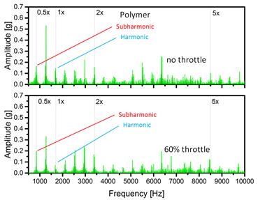
Fig. 11. Vibration amplitude spectra (in the Z-direction) of the
turbocharger, obtained at a rotational speed of 100,000 rpm for a polymer
compressor wheel
under different operating conditions
5. CONCLUSIONS
The
aim of this work was to carry out an experimental study to assess the dynamic
performance of the machine using rotating elements manufactured in a
conventional manner or by precise 3D printing technology. The disc used in the
tests was manufactured using MJP technology.
The
experimental research was conducted under conditions of reduced temperatures
using compressed air as the supply air. Accelerometers were used to measure
vibration amplitudes in two directions (X and Z). The research was carried out
at speeds between 10,000 and 105,000 rpm. The results of run-up tests as
well as a detailed vibration analysis of the turbocharger at elevated levels of
vibration and selected rotational speeds are presented. About the rotational
speeds that did not exceed 90,000 rpm, the use of the polymer disc had a
positive impact on the dynamic performance of the machine. At higher speeds,
the stall condition was observed regardless of the type of disc used. As for
the polymer disc, a decrease in the operating efficiency of the compressor was
observed at speeds greater than 100,000 rpm, which may have been caused by
deformation of the blades. In addition, the results obtained in the axial
direction of the turbocharger show that in the case of the aluminium disc,
during throttling of the flow, the oil whip instability phenomenon was
observed, and its occurrence confirmed. This phenomenon did not occur when the
polymer disc was being used.
Future
research will focus on flow optimisation using the manufacturing technology
described herein. A destructive test will also be performed.
References
1.
Javaid
Mohd, Abid Haleem. 2018. “Additive manufacturing applications in medical
cases: A literature based review”. Alexandria
Journal of Medicine 54(4): 411-422. DOI: 10.1016/j.ajme.2017.09.
2.
Yakout
Mostafa, Andrea Cadamuro, M.A. Elbestawi, Stephen C. Veldhuis. 2017. ,,The selection of process parameters in additive
manufacturing for aerospace alloys”. The
International Journal of Advanced Manufacturing Technology 92(5-8):
2081-2098. DOI: 10.1007/s00170-017-0280-7.
3.
Nejadpak
Ashkan, Yang Cai Xia. 2016. ,,A
vibration-based diagnostic tool for analysis of superimposed failures in
electric machines”. IEEE
International Conference on Electro Information Technology (EIT): 324-329. IEEE Region 4 (R4).
19-21 May 2016, USA. DOI: 10.1109/EIT.2016.7535260.
4.
Zieja
Mariusz, Paweł Gołda, Mariusz Żokowski, Paweł Majewski.
2017. „Vibroacoustic technique for the fault diagnosis in a gear
transmission of a military helicopter”. Journal of Vibroengineering 19(2): 1039-1049.
5.
Landry Michel, François
Léonard, Champlain Landry, Réal Beauchemin, Olivier Turcotte,
Fouad Brikci. 2008. ,,An improved vibration analysis
algorithm as a diagnostic tool for detecting mechanical anomalies on power
circuit breakers” IEEE Transactions
on Power Delivery 23(4): 1986-1994. DOI: 10.1109/TPWRD.2008.2002846.
6.
Xue Song, Ian Howard. 2018.
,,Torsional vibration signal analysis as a diagnostic tool for planetary
gear fault detection”. Mechanical
Systems and Signal Processing 100: 706-728. DOI:
10.1016/j.ymssp.2017.07.038.
7.
Graževičiūtė
J., I. Skiedraitė, V. Jūrėnas, A. Bubulis, V.
Ostaševičius. 2008. „Applications of high frequency vibrations
for surface milling”. Mechanika
1: 46-49.
8.
Ubartas
M., V. Ostaševičius, S. Samper, V. Jūrėnas, R.
Daukševičius. 2011. „Experimental investigation of vibrational
drilling”. Mechanika 4:
368-373.
9.
Vaičekauskis
M., R. Gaidys, V. Ostaševičius. 2013. „Influence of boundary
conditions on the vibration modes of the smart turning tool”. Mechanika 3: 296-300.
10.
Nguyen-Schäfer
Hung. 2015. “Vibrations of Turbocharger”. Rotordynamics of automotive turbochargers: 37-62. Germany: Springer
International Publishing. ISBN: 978-3-319-17644-4. DOI:
10.1007/978-3-319-17644-4.
11.
Chiavola
Ornella, Palmieri Fulvio, Recco Erasmo. 2018. “Vibration analysis to
estimate turbocharger speed fluctuation in diesel engines”. Energy Procedia 148: 876-883. DOI:
10.1016/j.egypro.2018.08.107
12.
Palúch
Stanislav, Peško Štefan, Majer Tomáš, Černý
Jan. 2015. „Transportation network reduction”. Transport Problems 10(2): 69-74. ISSN
1896-0596. DOI: https://doi.org/10.20858/tp.2015.10.2.7.
13.
Ascanio
G., W. Wang. 2007. “Diesel engine turbocharger performance monitoring
using vibration analysis”. 8th
International Conference on Engines for Automobiles. SAE Technical Paper
2007-24-0082. 16-20 September 2007, Italy. DOI: 10.4271/2007-24-0082.
14.
Crescenzo
Domenico, Viktor Olsson, Javier Arco Sola, Hongwen Wu, Andreas Cronhjort, Eric
Lycke, Oskar Leufven, Ola Stenlaas. 2016. ,,Turbocharger
speed estimation via vibration analysis”. SAE 2016 World Congress and Exhibition. SAE Technical Paper
2007-24-0082. 12-14 April 2016, USA. DOI: 10.4271/2016-01-0632.2016.
15.
Chaitanya
S Krishna, K. Madhava Reddy, Sai Naga Sri Harsha Ch. 2015. “Vibration
properties of 3D printed/rapid prototype parts”. Int. J. Innov. Res. Sci. Eng. Technol 4(6): 4602-4608.
DOI:10.15680/IJIRSET.2015.0406087.
16.
Andrearczyk
Artur. 2015. ,,The application of a photopolymer
material for the manufacture of machine elements using rapid prototyping
techniques”. Logistyka 4:
8628-8635.
17.
Kirk
R. Gordon, Alan A. Kornhauser, John, Alsaeed Ali Sterling. 2010.
“Turbocharger on-engine experimental vibration testing”. Journal of Vibration and Control 16(3):
343-355. DOI: 10.1177/1077546309103564.
18.
Andrearczyk
Artur, Paweł Baginski, Pawel Zywica. 2018. ,,Test
stand for the experimental investigation of turbochargers with 3D printed
components”. Mechanics and
Mechanical Engineering 22: 397-404.
Received 17.03.2020; accepted in revised form 19.05.2020
![]()
Scientific
Journal of Silesian University of Technology. Series Transport is licensed
under a Creative Commons Attribution 4.0 International License