Article
citation information:
Šteininger, J., Hrček,
S., Smetanka, L., Skyba, R. Optimisation procedure of inner geometry in spherical
roller bearings with regard to their durability. Scientific Journal of Silesian University of Technology. Series
Transport. 2020, 106, 173-181.
ISSN: 0209-3324. DOI: https://doi.org/10.20858/sjsutst.2020.106.15.
Ján ŠTEININGER[1],
Slavomír HRČEK[2],
Lukáš SMETANKA[3],
Rudolf SKYBA[4]
OPTIMISATION
PROCEDURE OF INNER GEOMETRY IN SPHERICAL ROLLER BEARINGS WITH REGARD TO
THEIR DURABILITY
Summary. This article deals with an optimisation procedure of
inner geometry of rolling elements designed for spherical roller bearings. A
process of selection of the most appropriate solution to increase spherical
roller bearing durability is understood under the term optimisation in this
case. The aim of this article is to examine the impact of a change of inner
geometry on the durability and reliability of spherical roller bearings
regarding production technology and competitiveness. Contact strain along with
a spherical roller by means of Finite Element Method (FEM) in contact points of
components of a spherical roller bearing by means of designed 3D parametric
models. The most appropriate shape of inner geometry of a bearing from the
standpoint of calculated durability will be determined based on the results of
analyses.
Keywords: spherical roller
bearing, rolling element, optimisation, contact strain
1. INTRODUCTION
Rolling bearings are an inseparable
part of most machines and devices, in which takes place rotational movement or
linear motion. There are different requirements on rolling bearings. Production
machines need bearings, which are able to work in high revolution, in power
engineering, bearings have to carry heavy loads, trains require bearings with
high-speed performance, etc.
Development or rather rolling
bearing optimisation is conditioned by an increase of technical parameters in
machines and devices. This fact refers especially to an increase of input
parameters such as power and revolution, weight and volume reduction, noise
level reduction, etc. However, the most important parameters requiring
optimisation are bearing lifetime and reliability.
The development of new technologies
introduces also new construction materials, new production techniques of
semi-finished products and bearing components or new installation methods. It
is important not to overlook the bearing construction. Here, it is possible to
perform geometry adjustment optimisation. This adjustment applies especially to
geometry adjustment of runways and rolling elements in the spherical roller
bearings.
2. SPHERICAL ROLLER BEARINGS
DURABILITY
The double-row angular
spherical roller bearing has a runway spherically ground on the outer ring. The
bearing is able to accommodate very high radial loads, as well as heavy axial
loads in both directions. High radial load capacity is caused by the great
number of rolling elements, so-called spherical rollers and their close contact
on the inner ring runways [2].
Rolling bearings
durability depends on a revolution number which the bearing can perform until
fatigue of any of their components takes place. A peeled material is a sign of
component fatigue. Fatigue is a basic and natural way of bearing damage. It is
demonstrated by the presence of small cracks under the bearing runway surface.
The depth of these cracks is usually about 0.05 - 0.3 mm depending on the
surface curve radiuses of rolling elements and the bearing rings runways. The
crack depth allows the material changes which are caused by slide pulsing
strain. This process leads to a gradual crack formation under the surface. It
can take quite a long time before it is visible on the surface in the form of a
peeled-off material, so-called pitting [1,6,7].
3. CONTACT STRAIN ALONG SPHERICAL
ROLLER IN SPHERICAL ROLLER BEARING
It is possible to
calculate the intensity of the contact pressure and the size of the contact
surface - effective length lef and width 2b from the contact
pressure distribution on the most strained point in the bearing inner ring. The
picture (Fig. 1) shows the course projection (the curve) of the contact
pressure along the contact surface lef of the contact ellipse on the
bearing inner ring. The contact strain curve was calculated using the finite
element method [5].
Fig. 1. The contact pressure course on the
inner bearing ring runway
4. PREPARATION OF PARAMETRIC 3D
MODEL AND CONTACT ANALYSIS
The double-row spherical
roller bearing model (Fig. 2) has been simplified to the maximum extent due to
the even load distribution on both rows and individual rolling elements. The
model consists of the rolling element, the outer ring, the inner ring, and the
contact surfaces. These surfaces are important for more precise model meshing
in FEM system ANSYS. The contact pressure was measured in the above-mentioned
parts [12].
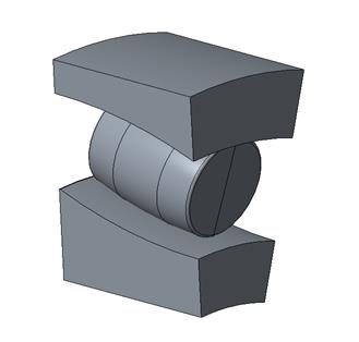
Fig. 2. The simplified model of
the double row spherical roller bearing
5. OPTIMISATION OF
GEOMETRY OF SPHERICAL ROLLER BEARING
The aim of optimisation
is a decrease of contact pressure that acts in the point of contact of the
rolling element with the outer and inner ring. The profile of a rolling
element will be optimised, and we also calculated the contact strain between
rolling elements and bearing rings [10].
We designed three new geometries
of the rolling element for spherical roller bearings that were consequently
compared with the reference profile. A selection of the most appropriate
design of the new geometry of the rolling element was based on
a comparison of volumes of contact pressures of bearing runways of the
inner and outer bearing rings.
The comparison of curves
of contact pressures of rolling elements depends on the length of the contact
surface lef. The pictures Fig. 3 (inner ring) and Fig. 4 (outer
ring) show the curve shape. We reached a decrease of contact pressure on
bearing runways of bearing rings in all designs of a new geometry of the
rolling element [11].
As shown in Figs. 3 and
4, the lowest contact pressure acts between two bearing rings and the rolling
element with new geometry 4. At the same time, contact pressure that acts
between bearing rings and the rolling element does not produce maximum strain
values that negatively affect bearing durability. The new geometry of the
spherical roller bearing formed by the logarithmic curve is the most
appropriate for optimisation of the spherical roller bearing regarding its
durability and lifespan [9].
The evaluation and selection of the
most appropriate design of the new geometry are shown in Tables 1 and 2.
Fig. 3. The comparison of
contact pressure courses in the bearing runway of the inner ring of the
spherical roller bearing of analysed geometries of the rolling element
Tab. 1
The evaluation of results of analyses in the inner
ring of the spherical roller bearing
|
Design nr. |
Title |
lef [mm] |
bef [mm] |
po [MPa] |
σmax [MPa] |
|
Reference bearing |
Profile |
21 |
0.96 |
2106.1 |
1426 |
|
1 |
The change of the main radius |
22.13 |
0.96 |
1921.5 |
1319.9 |
|
3 |
The combination of 2 radiuses |
22.14 |
0.64 |
2106.1 |
1315.3 |
|
4 |
Logarithmic
curve |
21.9 |
0.63 |
1948.3 |
1302.6 |
Fig. 4. The comparison of contact pressure
courses in the bearing runway of the outer ring of the spherical roller bearing
of analysed geometries of the rolling element
Tab. 2
The evaluation of results of
analyses in the outer ring of the spherical roller bearing
|
Design nr. |
Title |
lef [mm] |
bef [mm] |
po [MPa] |
σmax [MPa] |
|
Reference bearing |
Profile |
21.8 |
0.8 |
1758.4 |
1426 |
|
2 |
The change of the main radius |
22.14 |
1.21 |
2048.7 |
1319.9 |
|
3 |
The combination of 2 radiuses |
22.14 |
1.18 |
1719.7 |
1315.3 |
|
4 |
Logarithmic
curve |
22 |
0.64 |
1576.9 |
1302.6 |
For a better
evaluation of analysed geometries, we calculated the durability of individually
analysed geometries according to the Lundberg-Palmgren theory:
![]() (1)
(1)
![]() (2)
(2)
![]() (3)
(3)
where S is the probability of survival,
N- the number of load cycles, V- stressed
volume, e, c, h, A- material
constants defined by experiments, ![]() - pressure present in the contact point, 2b- the minor axis of the ellipse [12].
- pressure present in the contact point, 2b- the minor axis of the ellipse [12].
A calculation of
a total lifetime of the bearing was based on partial lifetimes of bearing rings.
As far as a logical comparison is concerned, 100 per cent lifetime is
assigned to the reference geometry. A comparison of the calculated
lifetimes of analysed geometries is shown in Fig. 5 [8].
5. CONCLUSIONS
Spherical roller
bearings can be optimised by a modification of the geometry of the rolling
element, that is, the spherical roller. The most appropriate geometry seems to
be the one formed by the logarithmic curve after a comparison of lifetimes
of the bearing with the new geometry of the rolling element (Fig. 5). The
logarithmic curve is described by equations while in this case,
a parameter of a loss of the logarithmic curve profile, that is,
a modified surface of the spherical roller. The optimal value of the
parameter is 0.00035 mm which is similar to the case of the rolling bearing
with the logarithmic profile [5,12,14].
The new geometry of the
rolling bearing composed by the logarithmic curve increases total carrying
capacity, and thus, bearing durability by more than 25 per cent. This new
geometry does not form strain peaks that negatively affect total bearing
durability.
Fig. 5. The comparison of calculated
lifetimes of analysed geometries
Acknowledgement
This
work was supported by Grant system of the University of Zilina and the Ministry
of Education, Science, Research and Sport under the contract No. 1/0595/18
– “Optimising the internal geometry of roller bearings with line
contact in order to increase their durability and reduce their structural
weight”.
References
1.
Bartnik Grzegorz,
Zbigniew Krzysiak, Waldemar Samociuk, Grzegorz Lysiak, Krzysztof Plizga, Marek
Szmigielski, Aleksander Nieoczym, Zdzislaw Kaliniewicz, Frantisek Brumercik. 2017.
“Documentation of meeting the requirements in the area of technical
safety on the example of distribution of liquid fuels”. Przemysl Chemiczny 96(5): 1039-1041. ISSN 0033-2496.
2.
Caban J., A. Marczuk, B. Sarkan, J. Vrabel. 2015. “Studies on
operational wear of glycol-based brake fluid”. Przemysł Chemiczny 94(10):
1802-1806. ISSN 0033-2496.
3.
Czech
Piotr. 2012. „Determination of the course of pressure in an internal
combustion engine cylinder with the use of vibration effects and radial basis
function - preliminary research”. Communications in Computer and
Information Science 329: 175-182. DOI
https://doi.org/10.1007/978-3-642-34050-5_21. Springer, Berlin, Heidelberg.
ISBN:978-3-642-34049-9. ISSN: 1865-0929. In: Mikulski Jerzy (eds), Telematics
in the transport environment, 12th International Conference on Transport
Systems Telematics, Katowice Ustron, Poland, October 10-13, 2012.
4.
Czech Piotr. 2011.
„Diagnosing of disturbances in the ignition system by vibroacoustic
signals and radial basis function - preliminary research”. Communications
in Computer and Information Science 239: 110-117. DOI
https://doi.org/10.1007/978-3-642-24660-9_13. Springer, Berlin, Heidelberg.
ISBN:978-3-642-24659-3. ISSN: 1865-0929. In: Mikulski Jerzy (eds), Modern
transport telematics, 11th International Conference on Transport Systems
Telematics, Katowice Ustron, Poland, October 19-22, 2011.
5. Drozdziel P., L. Krzywonos. 2009.
“The Estimation of the Reliability of the First Daily Diesel Engine
Start-up During its Operation in the Vehicle”. Eksploatacja i Niezawodnosc – Maintenance
and Reliability 1(41): 4-10. ISSN 1507-2711.
6.
Figlus Tomasz. 2019. “A method for
diagnosing gearboxes of means of transport using multi-stage filtering and
entropy”. Entropy 21(5): 1-13.
ISSN 1099-4300, DOI: 10.3390/e21050441.
7.
Figlus Tomasz, Mateusz Koziol. 2016. “Diagnosis of
early-stage damage to polymer - glass fibre composites using non-contact
measurement of vibration signals”. Journal
of Mechanical Science and Technology 30(8): 3567-3576. ISSN: 1738-494X.
DOI: 10.1007/s12206-016-0717-1.
8. Jedlinski
L., J. Caban, L. Krzywonos, S. Wierzbicki, F. Brumercik. 2015. “Application of vibration
signal in the diagnosis of IC engine valve clearance”. Journal of vibroengineering
17(1): 175-187. ISSN 1392-8716.
9. Kohár
R., F. Brumerčík, M. Lukáč, A. Nieoczym. 2016. „Numerical analysis of roller
bearing“.Applied computer science 12(1): 5-16. ISSN 1895-3735.
10. Krzysiak
Zbigniew, Grzegorz Bartnik, Waldemar Samociuk, Janusz Zarajczyk, Krzysztof
Plizga, Bartlomiej Rachwal, Slawomir Wierzbicki, Leszek Krzywonos, Frantisek
Brumercik. 2017. “Analysis of explosion hazard
at the liquid fuel station”. Przemysl
Chemiczny 96(2): 279-282. ISSN 0033-2496.
11. Mitka
M., R. Bastovansky, F. Brumercik, P. Ignaciuk. 2017. “Local resistance of heating molybdenum
sheet in a test device”. Advances
in science and technology-research journal 11(3): 87-93. ISSN
2299-8624.
12. Mruzek
Martin, Igor Gajdáč, Ľuboš Kučera, Dalibor Barta. 2016. „Analysis of parameters
influencing electric vehicle range“. Procedia Engineering 134: 165-174. ISSN 1877-7058.
13. Mruzek
Martin, Igor Gajdáč, Ľuboš Kučera, Tomáš
Gajdošík. 2017.
„The possibilities of increasing the electric vehicle range“. Procedia Engineering 192: 621-625. ISSN
1877-7058.
14. Tomasikova
M., M. Tropp, T. Gajdosik, L. Krzywonos, F. Brumercik. 2017. „Analysis
of transport mechatronic system properties”. 12th International Scientific Conference of Young Scientists on
Sustainable, Modern and Safe Transport. Procedia Engineering 192: 881-886. High Tatras, Slovakia, May
31-Jun 02, 2017. ISSN 1877-7058.
Received 18.10.2019; accepted in revised form 22.12.2019
![]()
Scientific
Journal of Silesian University of Technology. Series Transport is licensed
under a Creative Commons Attribution 4.0 International License