Article
citation information:
Mantič, M., Kuľka, J.,
Faltinová, E., Kopas, M., Lumnitzer, J. Simulation analysis of rope
belaying system. Scientific Journal of
Silesian University of Technology. Series Transport. 2019, 104, 107-117. ISSN: 0209-3324. DOI: https://doi.org/10.20858/sjsutst.2019.104.10.
Martin MANTIČ[1],
Jozef KUĽKA[2],
Eva FALTINOVÁ[3],
Melichar KOPAS[4],
Ján LUMNITZER[5]
SIMULATION ANALYSIS OF ROPE BELAYING SYSTEM
Summary. This article
describes a technical proposal of anchoring determined for a horizontal
belaying system, which was developed to increase the safety of crane operators
and maintenance staff in their movements and work at heights. This belaying
system can be installed either on the common, already existing footbridge of
the overhead travelling crane or on the crane track. Loading of the steel wire
rope was investigated by the simulation figurines during various assumed
loading regimes. The figurines were attached to the rope belaying system by
means of the standard personal protective equipment and the calculation process
was realised using the non-linear dynamic FEM analysis.
Keywords: rope, safety, non-linear dynamic FEM analysis,
simulation.
1. INTRODUCTION
Technical solution of the problems, which were presented in
this article, resulted from a requirement concerning safe entrance to the
crane-operator’s cab of a bridge crane as well as safe maintenance of the
crane and crane track. It is necessary to emphasise an important fact that
entry into the crane-operator’s cab, which is usually situated at a
height, as well as maintenance activities performed during the winter period
are especially dangerous with regard to the possibility of injury. Taking into
consideration the above-mentioned facts, it was developed in an original horizontal
rope belaying system, which is presented and analysed in this article, in the
form of a created simulation model. Under real conditions, this horizontal
belaying system (HBS) should be anchored using one of the three possibilities:
a)
anchoring between the
steel columns
b)
anchoring between the
concrete columns
c)
anchoring without the
columns by means of own supporting structure
Bearing capacity of the anchorage equipment of type C (this
is the category of the proposed equipment), which is considered as the value of
dynamic force, has to be 12 kN at least in accordance with the technical
standard STN EN 795. It was necessary, as the first step, to investigate what
heavy loading of the rope and joining elements corresponds to this force. There
were calculated reactions in the connecting points of the horizontal rope,
forces in the rope and deflection of the rope during loading by the vertical
force 12 kN, which is acting in various distances from the supports, using a
pre-load in the rope with the values from the interval 0.2 kN ÷ 20 kN.
At the same time, it was calculated as change of the rope pre-load value due to
an increase or decrease of the ambient temperature. The value of the anchorage
rope diameter, which was used for the calculations and also in the simulation
model, was 14 mm.
Various relevant aspects of the steel wire ropes were
presented in the corresponding literature. The publications [1, 2, 3] dealt
with steel wire ropes, taking into consideration the general principles of
their operation and safety. Possible causes of rope damage are described in
professional works [4, 5, 6, 7, 8]. Similarly, analyses of the stress state and
operational loading, as well as failure analyses of the steel wire ropes, are
shown in publications [9, 10, 11, 12]. Described in these papers [13, 14, 15],
are the mathematical and geometrical models developed for a computer simulation
of the steel wire ropes. The dynamic non-linear simulations, which were
performed using the Finite Element Methods (FEM), are presented in the articles
[16, 17, 18, 19, 20].
Original methods developed for the solution of questions
concerning mechanical vibrations and detection of failures occurring in the
mechanical systems are illustrated in the publications [21, 22].
2. MATERIALS AND METHODS
There are two possibilities in the case that the rope
belaying system is anchored along the crane track:
- anchoring to the steel columns of the hall (the
distance between the columns was 12 m and 18 m)
- anchoring to the supporting concrete columns of
the hall (the distance between the columns also was 12 m and 18 m)
Connection of the steel wire rope to the steel column of
the hall was achieved by means of the anchorage point, which was fixed to the
sidewall of the column, according to Fig. 1.
Fig. 1. Connection of the horizontal belaying
system to the sidewall of the column
Connection of the rope to the concrete column of the hall
(two concrete pillars arranged side-by-side) was realised by means of the
connecting bolts with the thread M12 in order to tighten the auxiliary
construction of the anchorage point, according to Fig. 2.
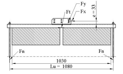
Fig. 2. Anchorage to the double concrete
column
There was a proposed new, own-developed supporting
structure determined for movement of the crane operating personnel or maintenance
staff on the crane, whereby the distance between the neighbouring supports was
5 m (Fig. 3).
The technical standard STN EN 795 defines the bearing
capacity for the analysed anchorage equipment of type C as the dynamic force
with the minimal value 12 kN. Other conditions, which must be fulfilled
according to Chapter 4.3.3 from the given technical standard, are as follows:
- the minimal strength of the rope has to be
two-times higher than the highest acceptable force, which occurs during
the capturing of a fall
- all other supporting components and anchorage
guide have to be dimensioned with regard to a double-value of the force,
which occurs in these parts during the capturing of a fall.
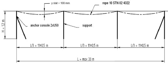
Fig. 3. Own-developed construction situated on the walkway
of the crane
The individual loading-level values, which were applied in
the strength calculations, respected the above-mentioned technical standard.
2.1. Simulation of loading for the HBS during fall of
persons – computational model
Calculation of loading for the HBS was realised according
to the crane user requirement, taking into consideration the real loading
conditions, that is, maximally 3 persons are moving on the walkway at the same
time and the maximal weight for each of them is 100 kg. The calculation
procedure was performed for the most unfavourable arrangement of the HBS, using
the steel wire rope with diameter Æ14 mm [21] and with span 18 m, whereby there is a
possibility that several workers are moving together within one section. The
computational model was created using the MSC Motion software, which is
specified for the solution of dynamic systems.
Mechanical characteristics of the belaying (anchoring) rope
and suspension component were simulated by a system of individual mass points
that represents the weight of the ropes and connecting elements. The stiffness
characteristics of the ropes are represented in the model by means of the
springs with the stiffness values corresponding to the applied components,
obtained by measuring. The persons (their human bodies) are simulated by means
of the anthropometric figurines. The complete computational model is
illustrated in Fig. 4.
Two stereometric computational models with different
simulation of figurine properties were created to represent a real situation.
Both models were investigated for various pre-load values of the belaying
ropes. The individual computational models are marked as follows:
o La14-18m-XXkN-LZ
– model with the stiff figurines
o Lb14-18m-XXkN-LZ
– model with the flexible figurines
where:
L means
application of the rope belaying system
a or b means
the method, which is currently used for simulation of the figurines (a - stiff,
non-flexible figurines, b - flexible figurines)
14 is
the belaying rope diameter (given in mm)
18m is
the belaying rope span (in m)
XXkN is the rope pre-load value (there were used the values 5,
10, 15 and 20 kN),
LZ means
the rope suspension component
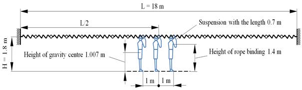
Fig. 4. Model of the belaying system with the figurines
These are the defined geometrical parameters of the
analysed belaying system:
- anchorage height of the belaying system above
the base is 1800 mm
- length of the rope suspension components is 700
mm
- the free length of the suspension rope before a
fall of the figurine is 120 mm + overhang of the rope ystat, max caused by
the own weight of the rope
- point of connection of the suspension rope to
the figurine is situated 1400 mm above the base
The stiff figurines used in the models “La...”
with the weight 100 kg were situated in the middle of span and with the mutual
distance 1 m. The height of the figurine is 1800 mm and the height of the
figurine gravity point is approx. 1007.3 mm. The distance of the figurines from
the belaying rope in the horizontal plane was 0.42 m (Fig. 5).
The figurines used in the models “Lb...”
are flexible in the waist around the transversal axis. The figurine waist is
positioned in the height 0.98 m from the figurine foot. A possible back-bend of
the figurine was eliminated using a bind between the bottom part of the
figurine and the figurine body (Fig. 6).
The calculation process considered such sequence of the
occurrences, by which the middle figurine was falling as the first and the
other figurines were falling gradually in the time interval 0.2 s. The most
unfavourable situation assumed a free movement of the figures without mutual
collisions during a falling.
2.2. Elaboration of the calculated
results
Considering the fact that eight (8) computational
models were investigated, the elaborated results of the performed computational
analyses are summarised in Tables 1 and 2, using the undermentioned designation
of the individual values.
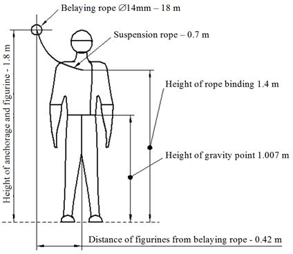
Fig. 5. Model of the stiff figurine
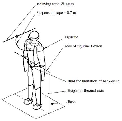
Fig. 6. Model of flexible figurine
The designation of the
used input parameters is:
G
[kg] weight
of the figurine
n
number
of the figurines
lz [mm] length of the
suspension component
hz [mm] height
of free figurine movement (free fall)
kz [N/mm] stiffness
of the suspension component (obtained from measurement in rope test-room)
Fo [kN] pre-load
of the belaying rope
The
designation of the calculated values is:
lzmax [mm] maximal
prolongation of the suspension component
Fz1 [kN] the
first dynamic response of tensile force in the suspension component at
beginning of the figurine fall (after tension of the suspension component)
Fzmax [kN] maximal dynamic
force in the suspension component (mostly the second response)
Fomax [kN] maximal
force in the belaying rope (pre-load + dynamic response)
ystat,max [mm] maximal
static overhang of the belaying rope (in fact, it is the first dynamic
deflection of the rope caused by its own weight; the figurines are motionless)
ystat+dyn [mm] the
highest calculated deflection of the belaying rope after fall of the figurines
It is possible to state, according to the results presented
in Tables 1 and 2, as well as after comparison of the forces Fomax with the
total deflections ystat + dyn that if the pre-load value is less than 20 kN.
Hence, the maximal dynamic force (occurring in the belaying rope) does not
exceed the value 30 kN, which is the maximal value of a force that is
acceptable with regard to the anchorage of the belaying rope.
Tab. 1
The results obtained
and elaborated from calculations for the models
La14-18m-XXkN-LZ
|
Model |
Load - stiff figurines |
Suspension component - rope of personal protective
equipment |
||||||
|
G [kg] |
n |
hp [mm] |
lz [mm] |
kz
[N/mm] |
lzmax [mm] |
Fz1 [kN] |
Fzmax [kN] |
|
|
La14-18m-5kN-LZ |
100 |
3 |
120 |
700 |
85,7143 |
38,14 |
1,35 |
3,26 |
|
La14-18m-10kN-LZ |
100 |
3 |
120 |
700 |
85,7143 |
39,9 |
1,17 |
3,47 |
|
La14-18m-15kN-LZ |
100 |
3 |
120 |
700 |
85,7143 |
41,438 |
1,28 |
3,57 |
|
La14-18m-20kN-LZ |
100 |
3 |
120 |
700 |
85,7143 |
36,3 |
1,33 |
3,13 |
|
Model |
Load – stiff figurines |
Belaying rope d = 14 mm, L = 18 m |
||||||
|
G [kg] |
n |
hp [mm] |
k [N/mm] |
Fo [kN] |
Fomax [kN] |
ystat,max
[mm] |
ystat+
dyn [mm] |
|
|
La14-18m-5kN-LZ |
100 |
3 |
120 |
214,5615 |
5 |
21,53 |
98,62 |
806,15 |
|
La14-18m-10kN-LZ |
100 |
3 |
120 |
214,5615 |
10 |
25,13 |
45,00 |
708,00 |
|
La14-18m-15kN-LZ |
100 |
3 |
120 |
214,5615 |
15 |
25,26 |
33,80 |
632,39 |
|
La14-18m-20kN-LZ |
100 |
3 |
120 |
214,5615 |
20 |
28,61 |
25,39 |
531,51 |
Tab. 2
The results obtained and elaborated
from calculations for the models
Lb14-18m-XXkN-LZ
|
Model |
Load - stiff figurines |
Suspension component- rope of personal protective
equipment |
||||||
|
G [kg] |
n |
hp [mm] |
lz [mm] |
kz
[N/mm] |
lzmax
[mm] |
Fz1 [kN] |
Fzmax [kN] |
|
|
Lb14-18m-5kN-LZ |
100 |
3 |
120 |
700 |
85,7143 |
37,86 |
1,35 |
3,23 |
|
Lb14-18m-10kN-LZ |
100 |
3 |
120 |
700 |
85,7143 |
32,31 |
1,88 |
2,76 |
|
Lb14-18m-15kN-LZ |
100 |
3 |
120 |
700 |
85,7143 |
30,67 |
1,718 |
2,64 |
|
Lb14-18m-20kN-LZ |
100 |
3 |
120 |
700 |
85,7143 |
33,99 |
1,658 |
2,90 |
|
Model |
Load – flexible figurines |
Belaying rope d = 14 mm, L = 18 m |
||||||
|
G [kg] |
n |
hp [mm] |
k [N/mm] |
Fo [kN] |
Fomax
[kN] |
vstat,max
[mm] |
vstat+
dyn [mm] |
|
|
Lb14-18m-5kN-LZ |
100 |
3 |
120 |
214,5615 |
5 |
21,38 |
98,62 |
802,42 |
|
Lb14-18m-10kN-LZ |
100 |
3 |
120 |
214,5615 |
10 |
24,645 |
50,55 |
755,00 |
|
Lb14-18m-15kN-LZ |
100 |
3 |
120 |
214,5615 |
15 |
28,383 |
33,80 |
733,12 |
|
Lb14-18m-20kN-LZ |
100 |
3 |
120 |
214,5615 |
20 |
30,054 |
25,39 |
634,16 |
Figures 7, 8 and 9 illustrate the time behaviours of the
calculated values F0, Fz and y for the model
“La14-18m-5kN-LZ” (stiff figurines, pre-load level 5 kN).
Fig. 7. Time behaviour of the tensile force in the belaying
rope
Fig. 8. Time behaviour of the tensile force in the
suspension rope
Fig. 9. Time behaviour of the overhang for
the belaying rope in the middle of span
4.
CONCLUSION
The analyses presented in this work were performed based on
information obtained from measurement of the stiffness characteristics
concerning the steel ropes or suspension components of personal protective
equipment used in the horizontal belaying system and from measurement of the
samples provided from the submitter of the given task. According to the
calculated results, it is possible to conclude that the dynamic loading, which
occurs during stoppage of the fall of two or three persons, is less than the
values determined by the technical standards [23] and [24]. If the pre-load
value is less than 20 kN, then the dynamic force, which is arising in the
belaying rope, does not exceed the value 30 kN, which is the maximal acceptable
force with regard to the anchorage of the belaying rope.
In view of the above-mentioned facts presented in the form
of the results obtained from the performed simulation process, it is possible
to point out that the analysed horizontal belaying system is a suitable
technical equipment that increases the safety of the crane service and
maintenance.
Acknowledgements
This article was elaborated in the framework of the Grant Project VEGA 1/0110/18.
References
1.
Boroška Ján, Jozef
Hulín, Oldřich Lesňák. 1982. Oceľové laná. [In Slovak: Steel ropes]. Bratislava: Alfa.
2.
Boroška Ján. 2000. „Činitele ovplyvňujúce životnosť a bezpečnosť prevádzky oceľových lán”. In: Výskum, výroba a použitie oceľových
lán: 15-21. [In Slovak: “Factors affecting the service life
and safety of steel wire ropes”. In: Research,
production and use of steel ropes: 15-21]. Faculty of Mining, Technical
University, Kosice, Slovakia. ISBN: 80-7099-592-0.
3.
Molnár Vieroslav. 2006. Oceľové
laná. [In Slovak: Steel ropes]. Kosice: Fakulty BERG, Technical University, Kosice,
Slovakia. ISBN 80-8073-629-4.
4.
Molnar Vieroslav, Gabriel
Fedorko, Beata Stehlikova, Peter Michalik. 2011. „Statistical
comparison of rope strands by ANOVA test and Kruskal-Walis test”.
Technics technologies education
management-TTEM 6 (4): 1121-1126. ISSN 1840-1503.
5.
Torkar M., B. Arzenek. 2002. „Failure
of crane wire rope”. Engineering
Failure Analysis 9(2): 227-233. ISSN 1350-6307.
6.
Costello George A. 2003. „Mechanics
of wire rope”. In: Wire & Cable Technical Symposium: 73rd annual
convention: 56-63. Wire Association International, Inc. May 2003. Atlanta,
Georgia, USA.
7.
Costello George A. 1997. Theory of Wire Rope. New York. Springer.
ISBN 0-357-98202-7.
8.
Chaplin Christopher
Richard. 1995. „Failure mechanisms in
wire ropes”. Engineering Failure
Analysis 2(1): 45-57. ISSN 1350-6307.
9.
Peterka Pavel, Jozef Krešák, Stanislav Kropuch, Gabriel Fedorko, Vieroslav Molnar, Marek Vojtko. 2014. „Failure analysis of
hoisting steel wire rope”. Engineering
Failure Analysis 45: 96-105. ISSN 1350-6307.
10.
Velinsky
S.A. 1985. „General nonlinear theory for complex wire rope“. International Journal of Mechanical Sciences 27(718): 497-507. ISSN0020-7403.
11.
Giglio Marco, Andrea Manes.
2005. „Life
prediction of a wire rope subjected to axial and bending loads”. Engineering Failure Analysis 12(4):
549-568. ISSN 1350-6307.
12.
Imrak C. Erdem, Erdönmez Cengiz. 2010. „On the problem of wire
rope model generation with axial loading”. Mathematical and Computational Applications 15(2): 259-268. DOI: https://doi.org/10.3390/mca15020259.
13.
Stanova Eva, Gabriel Fedorko,
Michal Fabian, Stanislav Kmet. 2011. „Computer modelling of wire strands
and ropes Part I: Theory and computer implementation”. Advances in Engineering Software 42(6):
305-315. ISSN 0965-9978. DOI: https://doi.org/10.1016/j.advengsoft.2011.02.008.
14.
Molnár Vieroslav,
Gabriel Fedorko,
Jozef
Krešák, Pavel Peterka,
Jana
Fabianová. 2017. „The influence of corrosion
on the life of steel ropes and prediction of their decommissioning”. Engineering
Failure Analysis 74: 119-132. ISSN 1350-6307. DOI: 10.1016/j.engfailanal.2017.01.010.
15.
Stolle Cody S., John Douglas Reid. 2011. „Development of a wire rope
model for cable guardrail simulation”. International Journal of Crashworthiness
16(3): 331-341. ISSN 1358-8265. DOI: 10.1080/13588265.2011.586609.
16.
Velinsky
S.A., G.L. Anderson, G.A. Costello. 1984. „Wire rope with complex cross
sections“. Journal of Engineerig
Mechanics 110(3): 380-391. ISSN 0733-9399.
17.
Imanishi Etsujiro, Takao
Nanjo, Takahiro Kobayashi. 2009. „Dynamic simulation of wire rope with contact”. Journal of Mechanical Science and
Technology 23(4): 1083-1088. ISSN 1976-3824.
18.
Paris
A.J., C.C. Lin, George A. Costello. 1992. „Simple cord composites“.
Journal of Engineerig Mechanics
118(9): 1939-1948. ISSN 0733-9399.
19.
Rudawska Anna, Hubert Debski.
2011. „Experimental and numerical analysis of adhesively bonded aluminium
alloy sheets joints”. Eksploatacja i Niezawodnosc – Maintenance
and Reliability 1(49): 4-10. ISSN 1507-2711.
20.
Gajdoš Ivan,
Ján Slota, Emil Spišák, Tomasz Jachowicz, Aneta Tor-Swiatek.
2016. „Structure and tensile properties evaluation of
samples produced by fused deposition modeling”. Open Engineering 6(1): 86-89. ISSN 2391-5439. DOI: https://doi.org/10.1515/eng-2016-0011.
21.
Zul'ová, Lucia, Robert
Grega, Jozef Krajňák. 2017. „Optimization of noisiness of
mechanical system by using a pneumatic tuner during a failure of piston
machine”. Engineering
Failure Analysis 79: 845-851. ISSN 1350-6307.
22.
Product catalogue of steel
wire ropes. Wire and rope production factory DRÔTOVŇA a.s.,
Hlohovec, Slovakia, 2001.
23.
STN EN 795: 1996. Osobné ochranné
prostriedky proti pádu z výšky. Kotviace zariadenia.
[In Slovak: Personal
fall protection equipment. Anchor devices]. Bratislava.
Slovak
Office of Standards, Metrology and Testing.
24.
STN EN 364+AC(832622):
1997. Osobné
ochranné prostriedky proti pádu z výšky. Kotviace
zariadenia. [In Slovak: Personal fall protection equipment. Testing methods].
Bratislava. Slovak Office of
Standards, Metrology and Testing.
Received 11.05.2019; accepted in revised form 17.08.2019
![]()
Scientific
Journal of Silesian University of Technology. Series Transport is licensed
under a Creative Commons Attribution 4.0 International License