Article
citation information:
Urbanský, M.,
Kaššay, P., Vojtková, J. New design solutions of tangential
pneumatic torsional vibration tuners. Scientific
Journal of Silesian University of Technology. Series Transport. 2019, 103, 183-191. ISSN: 0209-3324. DOI: https://doi.org/10.20858/sjsutst.2019.103.14.
Matej URBANSKÝ[1],
Peter KAŠŠAY[2],
Jarmila VOJTKOVÁ[3]
NEW
DESIGN SOLUTIONS OF TANGENTIAL PNEUMATIC TORSIONAL VIBRATION TUNERS
Summary. The optimal tuning of a mechanical system in terms
of torsional dynamics is a very important function of the flexible shaft
coupling, built in the system. Therefore, a flexible coupling with suitable
dynamic properties has to be carefully chosen for each specific application.
The main advantage of the pneumatic flexible shaft couplings, that is,
torsional vibration tuners, developed at our department, is that we can easily
regulate their dynamic properties, particularly their dynamic torsional
stiffness during the operation of a mechanical system. In order to improve our
pneumatic tuners in terms of better utilisation of their pneumatic flexible
elements and achieving specific operational properties, two new pneumatic
tuners with tangential arrangement of their pneumatic flexible elements were
designed. The aim of this article was to introduce these new pneumatic tuners,
protected by means of utility models, namely a tangential pneumatic flexible
shaft coupling with axially deformed flexible elements and tangential pneumatic
flexible shaft coupling with serial arranged flexible elements. Due to the fact
that both mentioned pneumatic tuners are not yet manufactured, this article
deals mainly with the principles and expected advantages of the pneumatic
tuners.
Keywords: tangential pneumatic torsional vibration
tuners, new design solutions, utility models, properties
1. INTRODUCTION
Nowadays, the reduction of
vibration and noise of machines is a very important task, mainly in terms of
human health, comfort and the lifetime and safety of machines, for example [6, 9, 14, 12]. Great emphasis is
placed on the use of modern progressive technologies in order to improve
electric and combustion engines for efficiency, better emissions and dynamics,
for example [4,
5, 10].
Flexible shaft couplings are the most utilised machine parts for the flexible
transmission of load torque in machines with rotary power transmission. A flexible coupling with
suitable dynamic properties, particularly dynamic torsional stiffness, has to
be carefully chosen for each specific application, otherwise dangerous
torsional vibration can occur in a mechanical system, for example [1, 7].
Flexible elements of flexible shaft
couplings are made of various materials, mainly of rubber, plastic and metal.
During the operation of mechanical systems, it is subjected to fatigue, ageing
of rubber and plastic flexible elements and ageing and wearing down of the
metal flexible elements of applied flexible coupling, for example [2, 8]. Consequently, the
applied flexible coupling loses its original dynamic properties and thus, the
ability to carry out its important functions in a torsionally oscillating
mechanical system, mainly, the tuning of a mechanical system in terms of
torsional dynamics. The disadvantages of the mentioned flexible elements can be
eliminated using pneumatic flexible elements (air-springs). The flexible
transmission of torque is ensured by a compressed gaseous medium, which does
suffer from fatigue or ageing. The main advantage of pneumatic flexible shaft
couplings (for example, couplings according to granted patents:
SK 288455 B6, SK 288344 B6, SK 288341 B6,
SK 278750 B6, SK 278653 B6, SK 278152 B6) is the
possibility to change their torsional stiffness which depends on the gaseous
medium pressure value in its pneumatic flexible elements. This makes it possible
to suitably adapt the dynamic torsional stiffness of a pneumatic coupling to
the actual operating mode of the mechanical system.
At our department, we dealt with
the development, research and application of pneumatic flexible shaft couplings
into mechanical systems. We focused mainly on continuous tuning of mechanical
systems during their operation in terms of torsional dynamics using pneumatic
flexible shaft couplings as active torsional vibration tuners. For continuous
tuning, we use electronic control systems developed by us. Our extensive
research in the field of pneumatic torsional vibration tuners and torsional
dynamics led to improvements in our pneumatic tuners and control systems. In
order to improve the tuners for better utilisation of their pneumatic flexible
elements and achieving specific operational properties, two new pneumatic
tuners with tangential arrangement of their pneumatic flexible elements were
designed. The aim of this article was to introduce these new pneumatic tuners,
protected by means of utility models, namely:
1. Tangential pneumatic
flexible shaft coupling with axially deformed flexible elements[4].
2. Tangential pneumatic
flexible shaft coupling with serial arranged flexible elements[5].
Because both mentioned pneumatic
tuners are not yet manufactured, this article deals mainly with the principles
and expected advantages of pneumatic tuners. We are going to manufacture and
research given pneumatic tuners within our next grant project.
2. NEW PNEUMATIC
TORSIONAL VIBRATION TUNERS
2.1. Tangential
pneumatic flexible shaft coupling with axially deformed flexible elements
Proposed tangential pneumatic
flexible shaft coupling with axially deformed elements (Fig. 1) is made up
of a driving (1) and a driven hub (2), flexibly connected by pneumatic flexible
elements (3). The pneumatic flexible elements are attached to support bodies
(4), which are rotatably mounted on pins (5). These pins are solidly connected
to the corresponding hub. The axes of the pneumatic flexible elements are
perpendicular to the axes of the pins. The support bodies (4) are fixed to the
pins with washers (6) and split pins (7). The rubber shells (8) of the flexible
elements are firmly connected to the support bodies with flanges (9).
A compressed gaseous medium (most
commonly air) is fed into the fuel space of the coupling via a filling valve
(12). The compression space of the coupling consists of inner spaces of the
pneumatic flexible elements, mutually interconnected with the inner spaces of
the support bodies. The pressure of the gaseous medium holds the unloaded
coupling in neutral position (Fig. 1). Under load by torque, it comes to
angular deflection between the driving and driven hub and consequently to axial
deformation of pneumatic flexible elements (Fig. 2).
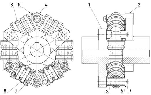
Fig. 1. The
tangential pneumatic flexible shaft coupling with axially deformed flexible
elements in unloaded state (neutral position)
The angular twist causes the
gaseous medium compression so the load torque can be transmitted flexibly. The
support bodies of the proposed coupling are automatically turned to the
equilibrium position so that only axial deformation of the elastic elements
occurs. In Fig. 3, we can see that in the case of conventional tangential
pneumatic flexible shaft couplings (with fixed support bodies), the flanges of
the elements are tilted during twisting.
Fig. 2. The
tangential pneumatic flexible shaft coupling with axially deformed flexible
elements in fully loaded state (at maximum twist angle α)
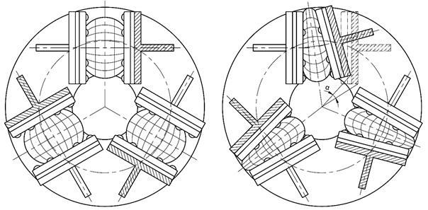
Fig. 3. A
tangential pneumatic flexible shaft coupling
a) in basic
position, b) in fully loaded state (at maximum twist angle α)
Since the flanges of the pneumatic
flexible elements are parallel in the full extent of the coupling’s
twist, it is possible to fully utilise the stroke of the pneumatic elements
given by their manufacturers, for example [2, 110]. Therefore, the
pneumatic flexible elements are deformed in the most suitable way with respect
to their design and lifetime. Another advantage of this type of coupling is
that the entire assembly of flexible elements connected by the support bodies
can be easily withdrawn from the pins, which allows easy and quick assembling
and disassembling of the whole coupling.
2.2. Tangential
pneumatic flexible shaft coupling with serial arranged flexible elements
Proposed tangential pneumatic flexible shaft
coupling with serial arranged flexible elements (Fig. 4) contains a driving flange (1)
and a driven flange (2). Between the flanges, the compression space of the
coupling is situated. The compression space of the coupling is comprised of
pneumatic flexible elements (3), (4), (5), which are arranged in a circle so
that they are connected and create a “flexible chain”. The flanges
of the pneumatic flexible elements (3) are fixed to rigid parts (6) of the
driving flange and to support bodies (7). The flanges of the pneumatic flexible
elements (4) are fixed only to the support bodies (7). The flanges of the
pneumatic flexible elements (5) are fixed to rigid parts (8) of the driven
flange and to the support bodies (7). The support bodies are fastened to
rotatable floating bodies (9) by pins (10). The rotatable floating bodies are
rotatably mounted on a pin (11). The pin (11) is coaxially embodied in the driven
flange (2).
|
|
|
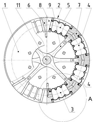
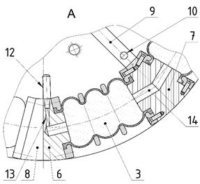
Fig. 4. The
tangential pneumatic flexible shaft coupling with serial arranged flexible
elements in unloaded state
Mutual interconnections of the
pneumatic flexible elements (3), (4), (5) are done by ducts (14), which are
created in the support bodies (7). The compression space of the coupling can be
filled with gaseous medium through valves (12) and valve ducts (13). If there
is overpressure of the gaseous medium in the pneumatic flexible elements
(compared to the atmospheric pressure) then the rigid parts (6) of the driving
flange and the rigid parts (8) of the driven flange are in contact, then the
unloaded coupling is in basic position (Fig. 4). Under load by torque, it
comes to an angular deflection between the driving and driven hub and
consequently to a deformation of the pneumatic flexible elements of the
pneumatic coupling. The angular twist causes the gaseous medium compression and
then the load torque can be transmitted flexibly in mechanical systems
(Fig. 5). The shape of the support bodies (Position 7 in Fig. 4)
can be adjusted so that the bearing surfaces of the pneumatic flexible elements
flanges are parallel at the maximum twist angle α of the coupling (Fig. 5), in order to maximise the
effective area of the compression space of the coupling and hence increase the
maximum load torque of the coupling.
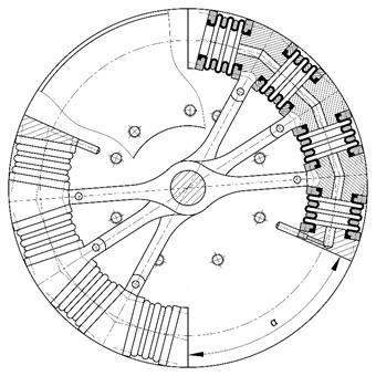
Fig. 5. The
tangential pneumatic flexible shaft coupling with serial arranged flexible
elements in fully loaded state (at maximum twist angle α)
The function of the support bodies
(7) in connection with the rotatable floating bodies (9) (Fig. 4) is to
ensure the stability of the “flexible chain” of pneumatic flexible
elements in the radial and axial direction (referred to the axis of rotation of
the coupling) when the coupling is twisted. In this way, much higher values of
the maximum twist angle α of the
coupling (Fig. 5) can be achieved (for example, compared to the tangential pneumatic
flexible shaft coupling shown in Fig. 3).
The high value of the maximum twist
angle of the coupling is one of the prerequisites for creating a high-flexible
coupling, which means flexible coupling with very low value of relative
torsional stiffness k0, can be expressed as follows:
![]() . (1)
. (1)
The k0 is defined as the ratio
of the nominal dynamic torsional stiffness of a flexible coupling kDN (at MN) to the nominal torque MN of the coupling. Common flexible couplings have the
relative torsional stiffness value in the range of
10 ÷ 30 rad-1. Shaft couplings marked as
high-flexible have the relative torsional stiffness value lower than
10 rad-1. Therefore, with respect to physical principles, a
flexible coupling with a low torsional stiffness must have a large twist angle in
order to transmit high load torque.
By the application of a
high-flexible coupling in a mechanical system (coupling 2 in
Fig. 6), the resonances from the individual harmonic components of a
torsional vibration excitation can be moved from the operating speed (n) range (OSR) of the system to the
lower speed area far enough under idle operating speed nV, for example [142]. This lower speed area
can be quickly run across at the start-up of a mechanical system, as shown in
the general Campbell’s diagram of a mechanical system (Fig.6), where i stands for the order of the
harmonic component of torsional vibration excitation.
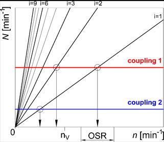
Fig. 6. Campbell’s
diagram of a mechanical system
3. CONCLUSION
The tangential pneumatic
flexible shaft coupling with axially deformed elements and the tangential pneumatic
flexible shaft coupling with serial arranged flexible elements can be applied in the
systems of mechanical drives. They allow flexible torque transmission and due
to the ability to change their torsional stiffness, ensure the tuning of these
systems at various operating conditions.
In the case of the tangential
pneumatic flexible shaft coupling with axially deformed elements, the pneumatic flexible
elements are deformed in the most suitable way in terms of their design and
lifetime and the
stroke of the pneumatic flexible elements is allowed to be fully utilised.
Regarding the tangential pneumatic
flexible shaft coupling with serial arranged flexible elements, the design is
focused on creating the high-flexible coupling, which means flexible coupling
with very low value of relative torsional stiffness. The current trend in the
field of flexible shaft couplings, which is the most noticeable in the
automotive industry, is the development and utilisation of high-flexible
couplings (dual
mass flywheels). Because gaseous media throughout its lifetime is not subject to ageing,
resultantly, pneumatic couplings do not lose their initial positive dynamic
properties, it would be of better advantage to develop flexible couplings with the
advantages of both pneumatic and high-flexible couplings.
On the above-mentioned grounds, we
suppose that both proposed pneumatic couplings are able to increase the
technical level and reliability of the mechanical systems in which they will be
applied. Therefore, we are going to research and manufacture the prototypes of the given
pneumatic couplings under the terms of our next grant project. Our research
will be focused on the following activities:
·
designing and manufacturing of specific
prototypes of the pneumatic couplings using the principles of presented utility
models,
·
measuring static [11] and
dynamic operating properties of the prototypes,
·
creating the mathematical and physical models of
the prototypes,
·
applying the prototypes into torsionally oscillating
mechanical systems, in order to do a tune and continuous tune the mechanical
systems during their operation in terms of torsional dynamics using pneumatic
flexible shaft couplings as active torsional vibration tuners and electronic
control systems developed by us,
·
creating the mathematical models of the torsionally oscillating
mechanical systems,
·
comparing the results of measurements with
results of the simulations of the torsionally oscillating mechanical systems
with the applied prototypes,
·
improving the mathematical and physical models
of the prototypes, if necessary.
Acknowledgement
This paper was written within the framework of the
APVV-16-0259 grant project entitled, Research and development of combustion
technology based on controlled homogenous charge compression ignition in order
to reduce nitrogen oxide emissions of motor vehicles.
This paper was written within the framework of the KEGA
041TUKE-4/2017 grant project entitled, Implementation of new technologies
specified for solving questions concerning the emissions of vehicles and their
transformation in educational processes in order to improve the quality of
education.
This paper was written within the framework of the VEGA
1/0473/17 grant project entitled, Research and development of technology for
homogeneous charge self-ignition using compression in order to increase engine
efficiency and to reduce vehicle emissions.
References
2.
Gurský
Pavol. 2011. „Influence of working cycles identification on
characteristics of flexible couplings and their comparison”. PhD thesis,
Košice, Slovakia: Technical University of Košice.
8.
Maláková
Silvia, Jaroslav Homišin. 2018. Defining of material characteristics for
flexible element in pneumatic flexible coupling. In Projektowanie, badania i eksploatacja. Volume 1, edited by
Jacek Rysiński, P. 277-282. Bielsko-Biala: Scientific Publisher of the
Academy of Technology and Humanities in Bielsko-Biala. ISBN 978-83-65182-93-7.
12.
Singhal
V., Jain S.S., Parida M. 2018. “Train sound level detection system at
unmanned railway level crossings”. European Transport/Trasporti
Europei 68(3): 1:18. ISSN 1825-3997.
13.
STN 011413:1992.
Mechanické
kmitanie – Pružné hriadeľové
spojky – Všeobecné požiadavky na
skúšky. [In Slovak: STN 011413:1992. Vibration – Resilient shaft
couplings – General requirements for tests]. Prague: Publisher of standards.
Received 10.02.2019; accepted in revised form 30.04.2019
![]()
Scientific
Journal of Silesian University of Technology. Series Transport is licensed
under a Creative Commons Attribution 4.0 International License