Article
citation information:
Kuľka, J., Mantič, M.,
Kopas, M., Faltinová, E., Hrabovský, L. Simulation-expertise analysis of
ropes used in the horizontal belaying system. Scientific Journal of Silesian University of Technology. Series
Transport. 2019, 103, 53-67.
ISSN: 0209-3324. DOI: https://doi.org/10.20858/sjsutst.2019.103.5.
Jozef KUĽKA[1],
Martin MANTIČ[2], Melichar KOPAS[3],
Eva FALTINOVÁ[4],
Leopold HRABOVSKÝ[5]
SIMULATION-EXPERTISE
ANALYSIS OF ROPES USED IN THE HORIZONTAL BELAYING SYSTEM
Summary. This article
deals with a dynamic simulation of the movement and fall of persons working at
a height, using the rope belaying system. The input data, which are necessary
for a created simulation model, were obtained from experimental measurements
realised from the concrete belaying system. The simulation analyses were
performed for three different values of the rope pre-load level. Consequently,
the outputs from the simulations presented in this article were applied in a
real design proposal of the rope anchoring arrangement for a horizontal
belaying system.
Keywords: rope, horizontal belaying system,
safety, FEM analysis
1. INTRODUCTION
Modern methods and
approaches, when applied within the individual phases of a machine whole life
cycle, particularly, during the phase of projection, design, operation,
repairs, maintenance and recycling, must take into consideration the safety
requirements. Presently, there remains in operation, a large number of aged
machines that were projected and produced several decades ago.
Although these machines
are suitable enough from the viewpoint of durability and functionality, they
are no longer reliable from the aspect of labour safety and health protection
with regard to new safety rules; taking into consideration conditions determined
for the safe movement of workers on the supporting structure of the given
machine equipment. Every user of such machines and machinery has to ensure
correction of occurred faults.
Operation and
maintenance of overhead travelling cranes, which operate in open-air weather
conditions, are typical examples with the above-mentioned problems. Entrance
into the crane operator’s cab, which is usually situated at a height, as
well as maintenance activities performed during the winter period, are especially
dangerous with regard to the possibility of injury.
Therefore, it is
necessary to install some suitable belaying system into the given working area
in order to make the movement of the operating personnel safer. Described in
this article, is the horizontal belaying system based on the application of
steel wire ropes. This belaying system was successfully installed in a real
bridge crane operation.
Various relevant aspects
of the steel wire ropes are presented in the corresponding literature. The
publications [1, 2] dealt with steel wire ropes, taking into consideration the
general principles of their operation and safety.
Possible causes of rope
damage were explained in professional works [3, 4, 5, 6, 7]. Similarly,
analyses of the stress state and operational loading, as well as failure
analyses of steel wire ropes have been published in other articles [8, 9, 10].
These were described in
the papers [11, 12], the mathematical and geometrical models developed for
computer simulation of steel wire ropes. The dynamic non-linear simulations,
which were performed using the Finite Element Methods (FEM), were presented in
these articles [13, 14, 15, 16, 17].
Specific approaches to
the solution of mechanical vibrations as well as to the detection of failures
in the various mechanical systems are illustrated in these publications [18, 19,
20].
2. MATERIALS AND METHODS
In this work, a special
horizontal belaying system (HBS), the horizontal rope belaying system, which
was proposed and applied in a real metallurgical plant was described and
analysed. This plant consists of several production halls equipped with various
kinds of bridge cranes. There exist three possibilities on how to realise
anchorage of the proposed rope belaying system:
a) anchoring between steel
columns.
b) anchoring between concrete
columns.
c) anchoring without columns.
Bearing capacity of the
anchoring equipment of the type C category (category of the proposed system),
which is given as the dynamic force value, has to be 12 kN at least according
to the technical standard STN EN 795. Hence, it was necessary to determine the
real loading of the rope and connecting elements or more precisely, investigate
what heavy loading of the rope and joining elements corresponds to this force.
There were calculated
reactions in the connecting points of the main rope (that is, horizontal rope),
forces in the rope as well as the deflection of the rope during loading caused
by the vertical force 12 kN. This vertical force was acting in various
distances from the supports using a pre-load in the rope with the values of the
pre-load forces from 0.2 kN to 20 kN. Simultaneously, it calculated a change of
the pre-load due to increase or decrease of the ambient temperature. The
diameter of the applied main rope was 14 mm.
The calculations were
performed by means of the Finite Element Method (FEM) and utilising the
software product COSMOS/M, version 2.7. The main rope Æ14 was simulated using the bar elements of type TRUSS2D [21].
2.1. Calculation
Methodology during Dynamic Loading of Anchorage Rope
The calculation model of
HBS, which was proposed for simulation of the static and dynamic loading of the
guide, is schematically illustrated in Fig.1. The horizontal guide PV (that is,
the main rope) is simulated by means of two-nodal planar bar elements
considering a non-linear elastic material and large displacements. These
elements are specified in the software, COSMOS/M, under the designation TRUSS2D
[21]. The same elements were used for simulation of the attachment rope SL.
An advantage of FEM is
the possibility of relatively easy simulation concerning other related parts,
which are situated within the supporting structure, taking into consideration
the stiffness of the whole system. In the simplest case, it was enough to apply
a solid connecting for the ends of the guide, according to Fig.1.
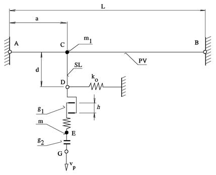
Fig. 1. Calculation
model of HBS with a stiff support of guide
The calculation model
also includes the single-node elements of the type MASS in order to simulate
the concentrated masses that replaced a ballast weight, which represents a
falling person (that is, the mass m in Fig.1) as well as to replace the snap
hook m1 of the attachment rope.
Also implemented into
the calculation model were elastic springs, which limits the horizontal
displacements of the ballast weight in order to eliminate a singularity. The
stiffness of these springs is very small (the stiffness value is k0 » 10-5 N/mm), which means,
mathematically, that a very small numerical value is substituted into the diagonal
element of the stiffness matrix so that a singularity of the given matrix can
be eliminated.
A free fall of the
ballast weight from height h was simulated by means of the contact elements of
the type GAP. These elements are two-node elements, which carry the load
unilaterally, either in pressure or in tension. At the same time, it is
possible to simulate the stiffness-damping characteristics of these elements in
such a way that the carried force is given by the following relation:
![]() ,
(1)
,
(1)
where F0 is
pre-loading force, k is stiffness of the spring, urel
is relative displacement of the nodes, u0 is relative
displacement at the beginning of the contact, vrel is
relative speed of the nodes, the constants c and s are the
damping characteristics.
The above-mentioned
properties enable the application of the GAP elements (in the case of a
parallel connection) also for simulation of the fall dampers. The elastic
properties of the elements were considered in this case only, whereby the value
of stiffness k was chosen as the highest value with regard to a minimal
influence on the dynamic response of the analysed system.
The stiffness of the
element g1, which is
situated between the attachment rope and the ballast weight, was defined as
10-times higher than the stiffness of the attachment rope.
A free fall of the
ballast weight was simulated using the contact element g2 with the vertical displacement vp, which was given in advance.
The solution of the
system response consists of two phases. Overhang of the guide, which is caused
by own weight, was determined in the first phase, using a static analysis and
applying the given initial pre-load. The response after the fall of the ballast
weight from height h was investigated
during the second phase, utilising the dynamic analysis applied for the given
configuration. The free fall of the load was simulated by a prescribed movement
of the nod G downward, whereby the
movement speed was significantly higher than the free fall speed.
The geometrical and
physical non-linearity was also taken into consideration during the
calculation. The geometrical non-linearity was given due to the unknown new
configuration of the system in every calculation phase. Therefore, the created
equations are non-linear with regard to unknown node displacements. The
physical non-linearity results from a non-linear dependence between the
deformation and the force in the rope.
The dynamic analyses
were performed by means of Newmark’s method. This implicit method enables
the inclusion of the damping characteristics of the contact elements in order
to simulate a fall damper. The value of time increments was chosen with regard
to the accuracy and stability of the solution. Every implicit method, that is,
including the Newmark’s method, offers a numerical stability of
calculation only in the case of linear methods. The numerical stability of the
calculation process can be lost during the solution of the non-linear methods
if the time step is chosen improperly, that is if it is too long. A possible
compromise offers the time increment, which is chosen from the interval 10-5
÷ 10-4 s. This was also applied in several performed analyses of
the Rayleigh damping:
![]() ,
(2)
,
(2)
whereby, in the matrix of damping C, it was considered the
coefficient a,
which is associated with the initial matrix of stiffness K0.
This coefficient was chosen from the range 0.001 ¸ 0.05. The damping, which is related to the matrix of mass M, was neglected, so the
coefficient b = 0.
The main task of this
analysis was to investigate the individual characteristics of the horizontal
belaying system in order to consider a necessity of changes concerning the
individual constructional modifications of the given system, which is utilised
in practice by the operator of the crane.
The individual analyses
were based on information obtained from realised measurements, principally from
information about the stiffness properties of the individual ropes and suspended
components of the personal protective equipment applied in the constructional
modifications of the horizontal belaying system. The tensile test was performed
in the case of the attachment textile rope with the diameter 11 mm and length
570 mm, which is delivered together with the safety belts of the type TIMUS
SAFETY: 048/414082023.
Working diagram of the
main rope Æ14 is presented in Fig.
2, working diagram of the textile attachment rope Æ 11 is given in Fig. 3 and the calculation of the working diagram of the
same rope is shown in Fig. 4.
The loading regimes of
the HBS were defined according to the technical standard STN EN 795. Evaluation
of the welding joints and screw joints in the individual constructional
modifications of the HBS was performed according to the STN EN 1993-1-8
(Eurocode 3: Design of steel structures. Part 1.8: Design of joints).
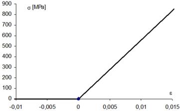
Fig. 2. Working diagram
of the rope Æ 14, used for
calculation
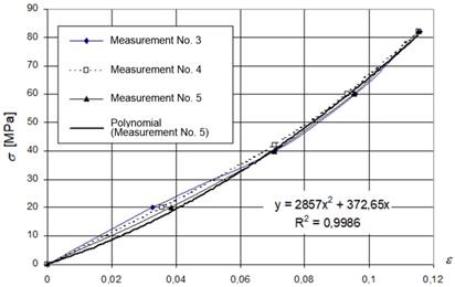
Fig. 3. Working diagram of the textile attachment rope Æ
11
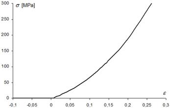
Fig.4. Calculation of the working diagram of the textile attachment rope
Æ
11
2.2. Deflection of Rope
2.2.1 Deflection of Rope Caused by Own Weight
The technical standard
STN EN 795 determines a bearing capacity of the HBS of type C as the minimal
dynamic force 12 kN. The main task of the performed calculations was to
investigate what a heavy loading of the rope and joining elements corresponds
to this force. There were calculated reactions in the connecting points of the
horizontal rope, forces in the rope as well as the deflection of the rope
during loading by the vertical force 12 kN. This vertical force was acting in
various distances from supports using the pre-load of the rope with the values
from 0.2 kN to 20 kN. Simultaneously, it was calculated as a change of the
pre-load due to increase or decrease of the ambient temperature. The modulus of
elasticity, EL, of the rope was measured during the tensile test, basically
this value is EL = 55835 MPa. The used coefficient of thermal expansion was 1.2
x 10-5 K-1. The nominal cross-sectional area of the applied rope is 69.17 mm2
and own weight of the rope is 0.64 kg m-1, according to the
catalogue of the rope producer [22]. The rope was anchored between the steel
columns.
The calculations were
performed by means of the FEM method, applying the software product COSMOS/M,
version 2.7. The main rope Æ14 was simulated using
the bar elements of the type TRUSS2D [21].
The values of the main
rope deflection, which is caused by own weight and by the pre-load forces
selected from the interval (0.2 kN ÷ 20 kN), are given in Tab. 1 (for
the rope with span length 12 m) and in Tab. 2 (for the rope with span length 18
m). Dependence of the main rope deflection on the pre-load force is illustrated
in Fig. 5.
These are the symbols
used in the tables:
L span length of the
rope.
F0 pre-load
of the rope at zero deflection (that is, pre-load without acting of the
weight).
v0 deflection of the rope
(deflection caused by the rope’s own weight).
v3 deflection
of the rope after increase of the ambient temperature about 50 K.
v4 deflection
of the rope after decrease of the ambient temperature about 50 K.
R1 force
in the rope at the deflection v0.
R3 force
in the rope after increase of the ambient temperature about 50 K.
R4 force
in the rope after decrease of the ambient temperature about 50 K.
Tab. 1
Deflection
of the rope with span length 12 m
|
L = 12 m |
|
|
|
|
|
|
|
F0 [kN] |
v0 [mm] |
v3 [mm] |
v4 [mm] |
R1 [kN] |
R3 [kN] |
R4 [kN] |
|
0,2 |
108,5 |
194,3 |
42,7 |
1,042 |
0,583 |
2,648 |
|
0,4 |
100,6 |
187,7 |
39,2 |
1,124 |
0,603 |
2,830 |
|
0,6 |
92,9 |
181,0 |
37,5 |
1,217 |
0,625 |
3,018 |
|
0,8 |
85,5 |
174,1 |
35,2 |
1,323 |
0,650 |
3,206 |
|
1 |
78,5 |
167,0 |
33,3 |
1,440 |
0,678 |
3,397 |
|
1,5 |
63,3 |
148,6 |
29,1 |
1,787 |
0,761 |
3,880 |
|
2 |
51,6 |
129,1 |
25,9 |
2,191 |
0,876 |
4,365 |
|
3 |
36,5 |
89,8 |
21,1 |
3,095 |
1,259 |
5,349 |
|
5 |
22,4 |
40,4 |
15,4 |
5,036 |
2,799 |
7,334 |
|
10 |
11,3 |
14,7 |
9,2 |
10,010 |
7,698 |
12,320 |
|
15 |
7,5 |
8,9 |
6,5 |
15,000 |
12,690 |
17,320 |
|
20 |
5,7 |
6,4 |
5,1 |
20,000 |
17,690 |
22,320 |
The graphs in Figures 6
and 7 illustrate rope deflection and influence of the changed temperature on
the pre-load value in the case of two rope lengths: 12 and 18 m. The line T 50
represents the percentage decrease of the force R1 after continual
increase of the rope temperature about 50 K, while line T –50
represents the percentage increase of this force after the decrease of the rope
temperature to about 50 K. It is evident that in the case of higher
pre-load level that there is reduced influence with the temperature changes.
Influence of the
temperature changes are important above all for such ropes, which are installed
out-of-door and exposed to weather conditions. The actual ambient temperature
should be taken into consideration during the initial pre-loading of the rope.
Tab. 2
Deflection
of the rope with span length 18 m
|
L = 18 m |
|
|
|
|
|
||
|
F0 [kN] |
v0 [mm] |
v3 [mm] |
v4 [mm] |
R1 [kN] |
R3 [kN] |
R4 [kN] |
|
|
0,2 |
189,5 |
304,8 |
91,4 |
1,343 |
0,836 |
2,783 |
|
|
0,4 |
179,1 |
295,7 |
86,1 |
1,420 |
0,862 |
2,953 |
|
|
0,6 |
168,9 |
286,4 |
81,3 |
1,507 |
0,889 |
3,128 |
|
|
0,8 |
158,8 |
276,9 |
76,9 |
1,602 |
0,920 |
3,306 |
|
|
1 |
149,5 |
267,2 |
72,9 |
1,707 |
0,953 |
3,487 |
|
|
1,5 |
126,6 |
242,4 |
64,4 |
2,010 |
1,050 |
3,949 |
|
|
2 |
107,4 |
216,6 |
57,5 |
2,367 |
1,175 |
4,423 |
|
|
3 |
79,4 |
164,7 |
47,2 |
3,201 |
|
5,388 |
|
|
5 |
50,1 |
87,0 |
34,6 |
5,080 |
2,924 |
7,355 |
|
|
10 |
25,4 |
33,0 |
20,6 |
10,020 |
7,717 |
12,330 |
|
|
15 |
16,9 |
20,0 |
14,7 |
15,010 |
12,700 |
17,320 |
|
|
20 |
12,7 |
14,4 |
11,4 |
20,010 |
17,690 |
22,320 |
|
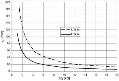
Fig. 5.
Dependence of the rope Æ14 mm deflection on the pre-load force
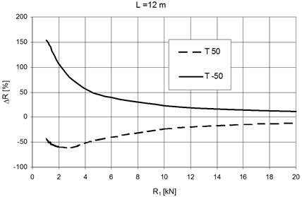
Fig. 6. Influence of changed temperature on pre-load
of rope with the length 12 m
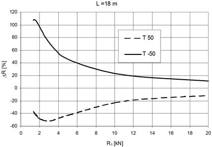
Fig. 7. Influence of changed
temperature on pre-load of rope with the length 18 m
2.2.2 Deflection of Rope Caused by the Loading
Force 12 kN
Deflection of the rope
in the point of action for the single vertical force with the value 12 kN
depends on the pre-load value R1 and on the point of action position
as well. Fig. 8 illustrates this dependence for the rope with length 12 m. The
symbol a, marks the distance of the point of action from the left end of the
rope. It is obvious that the position of the load influences the value of
deflection quite significantly, as such an influence of higher pre-load on
reduction of the deflection is non-significant.
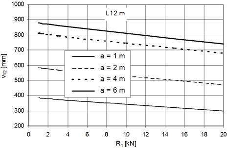
Fig. 8. Dependence of
deflection on the acting point of the force 12 kN
Analogical dependence of
the deflection on the load position, using various pre-load values for the rope
with length 18 m, is shown in Fig. 9.
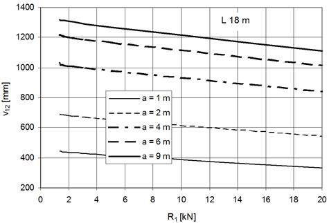
Fig. 9. Dependence of
deflection on point of action position for the rope with span length 18 m
A maximal deflection is
recorded if the load is situated in the middle of the span length. Dependence
of the deflection on the load position (which is given by the distance a,
measured from the left support) is non-linear, according to Fig. 10.
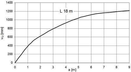
Fig. 10. Dependence of rope deflection on position of
the load (using the pre-load value 10 kN and span length 18 m)
2.3. Horizontal Belaying
System with Rope Æ 14 mm
The following values of
the input parameters were used in order to simulate the process of capture in
the case of the falling load
·
span length of the anchoring guide 12 m
·
mass of the falling balance weight 200 kg
·
length of attachment rope 600
mm
·
number of attachment ropes 2
·
free-fall height 300
mm
These values were
applied during the performed calculations, the already obtained characteristics
of the steel wire rope, which is used as the anchoring guide and the
characteristics of the textile attachment ropes.
These mechanical
properties described earlier were measured during the experimental tests.
According to the calculated results, it is safe to assume that the force in the
anchoring guide, as well as the force in the attachment rope, together with the
maximal deflection of the balance weight, depends on the pre-load level in the
anchoring guide. This is also presented as an influence of the attachment rope
position on the anchoring guide.
The graphs in Figures
11, 12 and 13 illustrate the influence of the attachment rope position, which
is given by the coordinate a (according to Fig. 1), on the dynamic response.
The highest force Fmax in the rope of the anchoring guide occurs in such
situation when the attachment rope is positioned in the middle of the guide
span length (Fig. 11). Analogically, the same is true for the maximal dynamic
deflection vmax of the ballast weight (Fig. 12). The highest force in the
attachment rope (in this case, it is a sum of the forces in the two attachment
ropes) occurs if the attachment rope is positioned at the end of the anchoring
guide (Fig. 13).
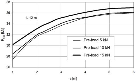
Fig. 11. Maximal force in the anchoring guide
rope with the span length 12 m
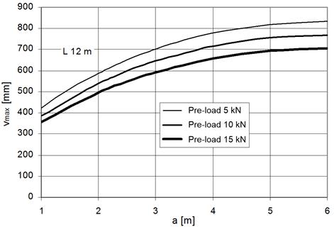
Fig. 12. Maximal deflection
of the rope with the span length 12 m
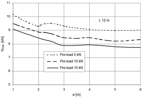
Fig. 13. Dependence of
maximal force in the attachment rope on its position
4. CONCLUSION
We introduced in this
article the possibility of increase labour safety of a specific machinery,
installed at a height, by means of a simple design solution and by use of
standard constructional components, for example, rolled shapes, rope, rope
clamps, rope sockets and tensioning screws.
The presented analyses were based on information
obtained from measurement of the stiffness properties of the ropes and
suspension elements which were utilised in the personal protective equipment
applied in the proposed design solutions of the HBS. It is presumed, according
to the obtained results, loading analyses and strength calculations of the given
HBS, that this system has the possibility of serving as anti-falling protection
for 2 or 3 persons. Hence, the dynamic loading of the HBS will be lower than as
defined in the technical standards [23] and [24].
The most unfavourable situation occurs if the
vertical loading force F is acting in the middle of the span length. The
limited application possibility of HBS is defined by internal prescriptions
based on the above-mentioned analyses and this requires an experimental
verification of the strength by means of a real test.
Acknowledgements
This article was elaborated in the
framework of the Grant Project VEGA 1/0110/18.
References
1.
Boroška Ján, Jozef
Hulín, Oldřich Lesňák. 1982. Oceľové laná. [In Slovak: Steel ropes]. Bratislava: Alfa. Publishing of technical and
economic literature.
2.
Boroška Ján. 2000. „Činitele ovplyvňujúce životnosť a bezpečnosť prevádzky oceľových lán”. Výskum, výroba a
použitie oceľových lán. [In Slovak: “Factors affecting the service life
and safety of the operation of steel ropes”. In Research, manufacture and use of wire ropes]. Faculty of Mining,
Technical University, Košice, Slovakia. ISBN: 80-7099-592-0.
3.
Torkar
M., B. Arzenek. 2002. „Failure of crane wire rope”. Engineering Failure Analysis 9(2):
227-233. ISSN 1350-6307.
4.
Costello
George A. 2003. „Mechanics of wire rope”. In Wire
& Cable Technical Symposium. 73rd
annual convention: 56-63. Wire
Association International, Inc. May 2003. Atlanta, Georgia, USA.
5.
Costello
George A. Theory of wire rope. New
York. Springer. ISBN 0-357-98202-7.
6.
Chaplin
Christopher Richard. 1995. „Failure mechanisms in wire ropes”. Engineering Failure Analysis 2(1):
45-57. ISSN 1350-6307.
7.
Starikov Maxim, Andrey
Beljatynskij, Olegas Prentkovskis, Irina Klimenko. 2011. “The use of
magnetic coercivity method to diagnose crane metalware”. Transport 26(3): 255-262.
8.
Velinsky
S.A. 1985. „General nonlinear theory for complex wire rope“. International Journal of Mechanical Sciences
27(718): 497-507. ISSN0020-7403.
9.
Giglio
Marco, Andrea Manes. 2005. „Life prediction of a wire rope subjected
to axial and bending loads”. Engineering
Failure Analysis 12(4): 549-568. ISSN 1350-6307.
10.
Imrak C. Erdem, Erdönmez Cengiz. 2010. „On the problem of wire rope model
generation with axial loading”. Mathematical
and Computational Applications 15(2): 259-268. DOI:
https://doi.org/10.3390/mca15020259.
11.
Stanova
Eva, Gabriel Fedorko, Michal Fabian, Stanislav Kmet. 2011. „Computer
modelling of wire strands and ropes Part I: Theory and computer
implementation”. Advances in
Engineering Software 42(6): 305-315. ISSN 0965-9978. DOI:
https://doi.org/10.1016/j.advengsoft.2011.02.008.
12.
Stolle Cody S., John Douglas Reid. 2011. „Development of a wire rope model
for cable guardrail simulation”. International
Journal of Crashworthiness 16(3): 331-341. ISSN 1358-8265. DOI:
10.1080/13588265.2011.586609.
13.
Velinsky,
S.A., G.L. Anderson, George A. Costello. 1984. „Wire rope with complex
cross sections“. Journal of
Engineerig Mechanics 110(3): 380-391. ISSN 0733-9399.
14.
Imanishi Etsujiro, Takao Nanjo, Takahiro Kobayashi. 2009. „ Dynamic simulation of wire rope with contact”. Journal of Mechanical Science and Technology 23(4): 1083-1088. ISSN 1976-3824.
15.
Paris
A.J., C.C. Lin, George A. Costello. 1992. „Simple cord composites“.
Journal of Engineerig Mechanics
118(9): 1939-1948. ISSN 0733-9399.
16.
Rudawska Anna, Hubert Debski. 2011.
„Experimental and numerical analysis of adhesively bonded aluminium alloy
sheets joints”. Eksploatacja i Niezawodnosc – Maintenance and Reliability
1(49):
4-10. ISSN 1507-2711.
17.
Gajdoš Ivan, Ján
Slota, Emil Spišák, Tomasz Jachowicz, Aneta Tor-Swiatek. 2016. „Structure and tensile
properties evaluation of samples produced by Fused Deposition Modeling”. Open Engineering 6(1): 86-89. ISSN 2391-5439. DOI: https://doi.org/10.1515/eng-2016-0011.
18.
Czech Piotr. 2011.
„Diagnosing of disturbances in the ignition system by vibroacoustic
signals and radial basis function - preliminary research”. Communications in Computer and Information
Science 239: 110-117. 11th International Conference on Transport Systems
Telematics (TST 2011). Katowice-Ustron, Poland, October 19-22, 2011. Modern Transport Telematics.
19.
Czech Piotr. 2012.
„Determination of the course of pressure in an internal combustion engine
cylinder with the use of vibration effects and radial basis function -
preliminary research”. Communications
in Computer and Information Science 329: 175-182. 12th International
Conference on Transport Systems Telematics (TST 2012). Katowice-Ustron, Poland,
October 10-13, 2012. Telematics In The
Transport Environment.
20.
Figlus Tomasz, Marcin
Stanczyk. 2016. “A method for detecting damage to rolling bearings in
toothed gears of processing lines”. Metalurgija 55(1): 75-78. ISSN:
0543-5846.
21.
Manual
to the software product COSMOS/M.S.R.A.C. Los Angeles. 2001.
22.
Product
catalogue of steel wire ropes. Wire and rope production factory
DRÔTOVŇA a.s., Hlohovec, Slovakia. 2001.
23.
STN EN 795: 1996. Osobné ochranné prostriedky proti pádu z výšky. Kotviace zariadenia. Bratislava. Úrad pre normalizáciu, metrológiu a skúšobníctvo Slovenskej republiky. [In
Slovak: STN EN 795: 1996. Personal fall
protection equipment. Anchor devices. Bratislava. Slovak Office of
Standards, Metrology and Testing].
24.
STN EN 364+AC(832622): 1997. Osobné ochranné prostriedky proti pádu z výšky. Kotviace zariadenia. Bratislava. Úrad pre normalizáciu, metrológiu a skúšobníctvo Slovenskej republiky. [In
Slovak: STN EN 364+AC(832622): 1997. Personal
fall protection equipment. Testing methods. Bratislava. Slovak Office of Standards, Metrology and Testing].
Received 03.03.2019; accepted in revised form 21.05.2019
![]()
Scientific
Journal of Silesian University of Technology. Series Transport is licensed
under a Creative Commons Attribution 4.0 International License