Article
citation information:
Szczucka-Lasota, B., Węgrzyn,
T., Lukaszkowicz, K. Low alloy steel shaft surface
regenerative welding with micro-jet cooling. Scientific Journal of Silesian University of Technology. Series
Transport. 2019, 102, 205-215.
ISSN: 0209-3324. DOI: https://doi.org/10.20858/sjsutst.2019.102.17.
Bożena SZCZUCKA-LASOTA[1],
Tomasz WĘGRZYN[2],
Krzysztof LUKASZKOWICZ[3]
LOW
ALLOY STEEL SHAFT SURFACE REGENERATIVE WELDING WITH MICRO-JET COOLING
Summary. In this
paper, the effect of surface preparation after innovating welding technology
with micro-jet cooling was reported. Substantial information about parameters
of steel machine elements surfacing with the micro-jet cooling process was
given. Recorded evidence concerning the influence of various micro-jet
parameters on the metallographic structure of the machine shaft after surface
welding was taken. There were tested metallographic and tribology properties of
welds. The tribology interactions of a solid shaft surfaces were examined after
surface welding.
Keywords: welding, micro-jet cooling, metallographic
structure, wearing
1. INTRODUCTION
The purpose of metal
surfacing is to obtain the best possible coating of the welding element.
Usually, after regeneration, machine components regain good operating
properties. Crankshafts are subjected to wear due to prolonged friction with
cooperating parts. For example, the shaft of the gearbox should be regenerated
in many vehicles after passing 150 Mm, and the shafts of mining heading
machines regenerate only after 4 months of intensive exploitation, unless the
head of the combine has contact with hard increments (then exploitation time of
mining combine elements will be even shorter) [1,2]. The surface welding
process is mainly and often used to apply hardness or wear-resistant layer of
base metal [3]. It is a very important method of extending the life of
machines, tools, and construction equipment. The main goal of the paper is to
explore the possibilities of surfacing with micro-jet cooling. For welding, the
machine parts with the use of micro-jet cooling, only welding processes in
which no slag is formed can be used. The biggest application of micro-jet
cooling takes place in the Metal Inert Gas (MIG), Metal Active Gas (MAG) and
Tungsten Inert Gas (TIG) processes. The metallographic structure was analysed
in terms of micro-jet parameters. For getting various amounts of ferrite,
bainite and martensite in this welding method, it is necessary to determine the
main parameters of the process such as:
·
the diameter of the stream of the micro-jet injector.
·
type of micro-jet gas or gas mixture.
·
micro-jet gas
pressure.
·
a number of jets.
Welding with micro-jet
technology was very carefully tested for low alloy welding [4,5]. In low alloy
steel weld, mechanical properties of weld correspond with the chemical
composition and metallographic structure [6,7]. In the case of hardfacing, it
is important to obtain a martensitic structure in order to increase the
hardness of the coating and their resistance to abrasive wear [8-10].
The goal of this paper
is to describe the possibilities of shaft MAG surface welding process with
micro-jet cooling, which allows obtaining the various content of ferrite,
martensite, bainite. In the case of ferrite, it is important that the grain is
not as small as possible, which translates into better tribological properties
of regenerated shafts and does not lead to fissures. In weld metal deposit
there are three morphological varieties of ferrite: grain boundary ferrite,
side place ferrite and acicular ferrite, which is the most advantageous due to
the small grain size.
2. MATERIALS AND METHOD
A test stand for hardfacing was
made. To obtain the various amount of ferrite, martensite and bainite in shaft
surface weld, it was installed through a welding process with micro-jet
injector with a variable number of micro-streams. The diameter of streams was
on the level of 50 µm and 60 µm. To analyse the surface welding
with micro-jet cooling, there were chosen shafts of 40NiCrMo6 steel with a diameter
of 34 mm. An example of a machine shaft supplied for regenerative welding with
the use of micro-jet cooling is shown in Figure 1.
Surface weld was
prepared by welding with micro-jet cooling with varied parameters. Two
micro-jet gases (nitrogen and helium) were tested in the cooling process just
after surface welding. There were also other varied important micro-jet
parameters: gas pressure, micro-jet gas pressure and micro-jet diameter. The
main data about the parameters of welding were shown in Table 1. MAG surface
welding process with micro-jet cooling was carefully tested. Helium was chosen
for the micro-jet cooling because of its good cooling properties. Nitrogen was
used for the micro-jet cooling, under the assumption that there could be observed
slight nitriding of the surface welds.
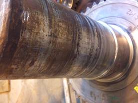
Fig. 1.
A
machine shaft supplied for regenerative welding with the use of micro-jet
cooling
Tab. 1
Parameters
of the welding process.
|
No. |
Parameter |
Value |
|
1. |
Diameter of wire |
1.2 mm |
|
2. |
Standard current |
220 A |
|
3. |
Voltage |
24 V |
|
4. |
Shielding welding gas |
80%Ar+20%CO2 |
|
5. |
Kind of tested
micro-jet cooling gas |
1 – He |
|
6. |
Micro-jet gas pressure |
0.4 MPa |
|
7. |
Micro-jet diameter |
50 µm |
3. RESULTS AND DISCUSSION
A goal of the study was
to examine the varying structure of the typical surfacing shaft after welding.
Steels with a carbon content of about 0.3% should be preheated to a temperature
of about 200℃. The possibility of welding cracks
in these steel grades is caused by the presence of such structures in Weld
Metal Deposit (WMD) as martensite, bainite and grain boundary ferrite. Such a
structure can promote cracking after welding. Nevertheless, it was decided to
check the possibility of surface welding steel shaft without preheating due to
the use of micro-jet cooling, thinking that it might reduce the size of ferrite
significantly. Micro-jet gas could have both influence on cooling conditions
and the chemical WMD composition (nitrogen amount in WMD) (Figures 2, 3 and 4).
Important t8/5 welding parameter, which
informs about the cooling time between 800 and 500°C, where the most
important austenite transformation occurs, is the largest (on the level of 10
sec) when micro-jet cooling is not used.
In the case of t8/5
welding parameter, it is much smaller (on the level of 6 sec) when nitrogen
micro-jet cooling is used.
Fig. 2. Weld cooling conditions without micro-jet cooling
Fig. 3. Weld cooling conditions with micro-jet cooling, micro-jet gas (N2)
pressure is 0.5 MPa, one jet installed in the injector
Fig. 4. Weld cooling conditions with micro-jet cooling, micro-jet gas
(He) pressure is 0.5 MPa, one jet installed in injector
In the case of t8/5
welding parameter, it is also smaller (on the level of 4 sec) when helium
micro-jet cooling is used. Heat transfer coefficient of tested micro-jet gases
influences on cooling conditions of welds (Figures 3 and 4). This corresponds
to varied martensite content. This is due to the different conductivity
coefficients (λ·105), which for N2
and Ar, in the 273 K is on the level of 23.74 J/cm·s·K. Helium
gives much stronger cooling conditions due to the higher conductivity
coefficients (λ·105), which for He is 143.4
J/cm·s·K. A typical WMD had similar chemical composition in all
tested cases. The chemical composition of WMD after MAG welding with and
without micro-jet cooling is presented in Table 2.
Tab. 2
Chemical
composition of Weld Metal Deposit (WMD)
|
No. |
Element |
Amount |
|
1. |
C |
0.31% |
|
2. |
Mo |
0.2 |
|
3. |
Mn |
0.67% |
|
4. |
Si |
0.17% |
|
5. |
P |
0.014% |
|
6. |
S |
0.011% |
|
7. |
Cr |
1.8% |
|
8. |
Ni |
1.36% |
|
9. |
Cu |
0.07% |
|
10 |
Al |
0.22% |
|
11. |
V |
0.01% |
|
12. |
N |
55-70 ppm |
For standard MAG welding
without micro-jet cooling and for MAG welding with helium micro-jet cooling,
the amount of nitrogen was always on the level of 55 ppm. For MAG welding with
nitrogen micro-jet gas cooling, the amount of nitrogen was much higher, on the
level of 70 ppm. After chemical analyses, the metallographic structure was
given. Presence of such structures in WMD as martensite, bainite and grain
boundary ferrite were identified. Weld cracks were not observed in all examined
cases, especially where micro-jet cooling was used. An additional success of
the research was the possibility of controlling the martensite content. For the
sake of transparency in the interpretation of results, it was decided to
compare only the content of martensite in the weld. A piece of information
about martensite amount in WMD is shown in Tables 3 and 4.
Tab. 3
Martensite
in surface weld (helium used as a micro-jet gas)
|
Micro-jet diameter, µm |
Micro-jet gas
pressure, MPa |
Number of jets |
Martensite aprox, % |
|
- |
- |
- |
45 |
|
50 |
0.4 |
1 |
50 |
|
50 |
0.4 |
2 |
60 |
|
50 |
0.5 |
1 |
55 |
|
50 |
0.5 |
2 |
65 |
|
60 |
0.4 |
1 |
55 |
|
60 |
0.4 |
2 |
65 |
|
60 |
0.5 |
1 |
60 |
|
60 |
0.5 |
2 |
65 |
Tab. 4
Martensite
in surface weld (nitrogen used as a micro-jet gas)
|
Micro-jet diameter, µm |
Micro-jet gas
pressure, MPa |
Number of jets |
Martensite aprox, |
|
- |
- |
- |
45 |
|
50 |
0.4 |
1 |
50 |
|
50 |
0.4 |
2 |
55 |
|
50 |
0.5 |
1 |
55 |
|
50 |
0.5 |
2 |
60 |
|
60 |
0.4 |
1 |
55 |
|
60 |
0.4 |
2 |
60 |
|
60 |
0.5 |
1 |
60 |
|
60 |
0.5 |
2 |
65 |
Micro-jet cooling does
not have a greater influence on the chemical composition of the weld. In the
case of nitrogen micro-jet cooling, there was additionally observed traces of
nitrides. It was observed that the micro-jet cooling is able to increase the
content of martensite to 65% and seriously reduce the size of ferrite grains
(Figures 5 and 6).
It is not so easy to
precisely count martensite amount such as other typical low alloy steel weld
phases: acicular ferrite, grain boundary ferrite, side plate ferrite for low
alloy welding [11]. Martensite amount was only estimated. Cooling allows for the
increase of the content of the martensite in the weld from 45% to 65%. After
microscope observation, a microhardness was carried out (Figures 7, 8 and 9). Standard
surface welding could not guaranty high hardness (Figure will be able to be
integrated in 8).
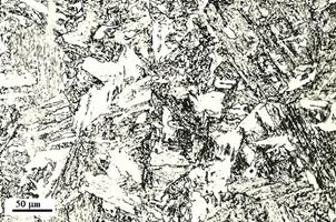
Fig. 5. Martensite
(approximately 45%) in weld after MAG welding without micro-jet cooling (big
size of ferrite grains)
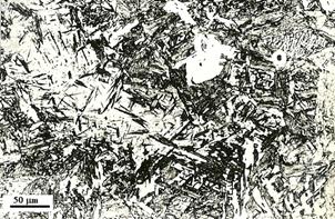
Fig. 6. Martensite (approximately.
65%) in weld after MAG welding with micro-jet cooling (ferrite
grain of various sizes)
Surface weld hardness of
the shaft was decreased in terms of the distance from weld face; the maximum
value was much below 450 HV. Much higher hardness values were observed after
welding with helium micro-jet cooling (Figure 8).
Surface
shaft welding with helium micro-jet cooling allowed to excide hardness even
above 450 HV. The effect of nitrogen micro-jet cooling on steel WMD hardness is
shown in Figure 9.
Surface
shaft welding with nitrogen micro-jet cooling allowed to excide hardness even
above 450 HV. This is translated by increased nitrogen content in WMD (from 55
ppm to 70 ppm). Finally, tribological tests were done using the Amsler machine. Results
of the Amsler tests are shown in Table 5.
Tab. 5
The tribological test
results
|
Properties |
Sample of surface weld without micro-jet cooling |
Sample of surface weld with helium micro-jet cooling |
Sample of surface weld with nitrogen micro-jet
cooling |
|
Critical Force |
300 N |
300 N |
300 N |
|
Critical unit
pressure |
9.74 N/mm2 |
9.74 N/mm2 |
9.74 N/mm2 |
|
Blurring time |
10 s |
25 s |
25 s |
|
Friction
coefficient |
0.548 |
0.397 |
0.380 |
|
Weight loss [g] |
0.0160 g |
0.0009 g |
0.0006 g |
Based on the results
stated in Table 6, it was found that the highest resistance to abrasive wear
has the sample taken after welding with micro-jet cooling. Favourable micro-jet
gases are nitrogen or helium.
After hardness analysis, Charpy
V impact test of the deposited metal was carried out. The Charpy tests were
done at temperature +20°C on 5 specimens having been extracted from each
weld metal (Table 6).
Fig. 7. Hardness of
standard MAG steel weld without micro-jet cooling
Fig. 8. Hardness of weld
after with micro-jet cooling with helium used as micro-jet gas
Fig. 9. Hardness of weld
after micro-jet cooling with nitrogen used as a micro-jet gas
Tab. 6
Impact toughness for MIG welding with varied
micro-jet gases
|
Welding process |
Impact toughness KV [J] |
|
MAG |
70 |
|
Mag with helium
micro-jet cooling |
75 |
|
Mag with nitrogen
micro-jet cooling |
65 |
The impact toughness of all WMD is comparable among
themselves. The impact toughness of this steel (with 0.31% C) is not very high,
however, the influence of micro-jet cooling on the elastic properties of steel
can be lightly noticed. Helium micro-jet cooling shreds the ferrite grain,
which can lead to a small increase in impact strength. Cooling with nitrogen
micro-jet cooling allows nitrogen to be increased in WMD, which adversely
affects elastic properties of the material. Helium with minimal could be
regarded as a good choice.
After
the impact toughness analysis, a fractography test was conducted. Fractographic
methods are routinely used to determine the cause of failure in engineering
structures. Figure 10 presents a typical fracture of the WMD after MAG welding
without micro-jet cooling. Figure 11 shows a typical fracture of the WMD after
MAG welding with helium micro-jet cooling.
Comparing
both drawings, it is possible to deduce that after welding with helium micro-jet cooling fracture of
WMD is more ductile than after welding with nitrogen micro-jet cooling.
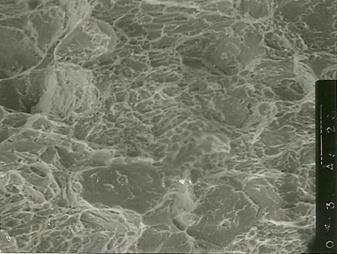
Fig.
10. Scanning electron micrograph of small-sized
inclusions in the WMD after welding with nitrogen micro-jet cooling
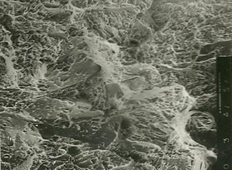
Fig.
11. Scanning electron micrograph of small-sized
inclusions in the WMD after welding with helium micro-jet cooling
4. CONCLUSIONS
The micro-jet surfacing
technology was tested for surface welding with various micro-jet parameters.
Micro-jet technology could be treated as a very beneficial process during shaft
surfacing. Structure change was observed, especially the increase in martensite
content and ferrite fragmentation in the metal deposit.
On the basis of the
investigation it is possible to deduce that:
· micro-jet-cooling could
be treated as an important element of MAG welding process.
· it is possible to steer
the metallographic structure (martensite, nitrides).
· it is possible to steer
the weld harness by various micro-jet parameters.
· there is no great
difference between the influence of argon and helium on cooling conditions.
· nitrogen used for
micro-jet cooling (instead of argon and nitrogen) is responsible for the
highest hardness in all tested.
· there were observed
traces of nitrides when nitrogen was used for micro-jet cooling (instead of
argon when nitrides were not observed).
· the highest resistance
to abrasive wear has the sample taken after welding with micro-jet cooling.
· micro-jet cooling does
not have a noticeable influence on the impact toughness of WMD.
References
1.
Evans
G.M. 1994. ”Microstructure and
properties of ferritic steel welds containing Al and Ti”. Oerlikon-Schweissmitt 130: 21-39.
2.
Krayushkina
K., O. Prentkovskis, A. Bieliatynskyi, R. Junevičius. 2012. “Use of
steel slags in automobile road construction”. Transport 27(2): 129-137.
3.
Burdzik R., Ł. Konieczny, Z. Stanik, P. et al. 2014.
“Analysis
of impact of chosen parameters on the wear of camshaft”. Archives
of Metallurgy and Materials 59(3): 957-963. DOI:
10.2478/amm-2014-0161.
4.
Fornalczyk A., J. Willner, J. Cebulski et al. “Structure and
surface state of different catalytic conveters applied in cars”. The 5th
international Lower Silesia-Saxony conference “Advanced Metal Forming
processes in automotive industry (AutoMetForm 2016)”. Wroclaw, Poland, 28-29 June 2016. P. 327-333.
5.
Aleksić V., M. Dojčinović, L. Milović, I.
Samardžić. 2016. „Cavitation
damages morphology of high-strength low-alloy steel”. Metalurgija 55(3): 423-425.
6.
Kasuya T., Y. Hashiba, S. Ohkita, M. Fuji.
2001. “Hydrogen distribution in multipass submerged arc weld
metals”. Science and Technology of Welding and Joining 6(4): 261-266. DOI: 10.1179/136217101101538767.
7.
Hadryś
D. 2015. “Impact load of welds after micro-jet cooling”. Archives
of Metallurgy and Materials
60(4): 2525-2528.
8.
Bąkowski
H. 2018. “Wear Mechanism of spheroidal cast iron piston ring-aluminum
matrix composite cylinder liner contact”. Archives of Metallurgy and Materials 63
(1): 481-490. DOI: 10.24425/118965.
9.
Sozańska M., A. Maciejny, C. Dagbert et al. 1999. “Use of quantitive metallography in
the evaluation of hydrogen action during martensitic transformations”. Materials Science and Engineering 273-275: 485-490. DOI: 10.1016/S0921-5093(99)00333-0.
10.
Grazeviciute J.,
I. Skiedraite, V. Jurenas, A. Bubulis, V. Ostaševičius. 2008.
“Applications of high frequency vibrations for surface milling”. Mechanika (1): 46-49.
11.
Hadryś
D. 2016. “Mechanical properties of plug welds after micro-jet cooling”.
Archives
of Metallurgy and Materials 61: 1771-1775.
Received 09.10.2018; accepted in revised form 29.12.2018
![]()
Scientific
Journal of Silesian University of Technology. Series Transport is licensed
under a Creative Commons Attribution 4.0 International License