Article
citation information:
Hadryś, D., Kubik, A., Stanik,
Z., Łazarz, B. Deceleration and deformation during dynamic load of model longitudinals –
real conditions and simulation. Scientific
Journal of Silesian University of Technology. Series Transport. 2019, 102, 53-64. ISSN: 0209-3324. DOI: https://doi.org/10.20858/sjsutst.2019.102.4.
Damian HADRYŚ[1], Andrzej KUBIK[2], Zbigniew STANIK[3], Bogusław
ŁAZARZ[4]
DECELERATION AND DEFORMATION DURING DYNAMIC LOAD OF MODEL LONGITUDINALS - REAL CONDITIONS AND SIMULATION
Summary. The manner and degree of
taking over impact energy by the passive safety elements of the vehicle body is
the basis for providing conditions for the survival of people using the means
of transport (driver and passengers). The elements specially designed for this
purpose in the self-supporting body are longitudinals. Their energy-absorbing
properties are designed by using a specific shape, by using appropriate
connections of their components and by choosing the right material. Determining
the degree to which the vehicle (body) ensures safety during collision requires
testing. The most complex and expensive tests are the ones carried out on a
complete real object (whole vehicle). The solution worth considering is a bench
test of individual body elements designed as energy-consuming (for example,
longitudinals). In addition, it is also possible to carry out computer
simulations in this area. The purpose of this article was to present and
compare the results of dynamic studies on model energy-consuming real objects
and compare the results obtained this way with the results of computer
simulation in the same range. The scope of work was adopted on this basis:
passive safety, model energy-absorbing elements of steel self-supporting
vehicle body, dynamic tests, computer simulations. For the purpose of this
study, a model of vehicle passive safety elements (model longitudinals) was
designed for which dynamic tests were carried out on a specially designed test
stand (speed of the hammer was up to 9.7 m/s, impact energy was up to 23.6 kJ).
This test stand enabled registration of the deceleration during impact and
deformation of the tested object. Next, computer simulations were carried out
for geometrically and material-identical models. On the basis of the conducted
tests, it was found that it is worth considering the replacement of collision
tests of the whole vehicle by tests of its individual components. These tests
can also be supported by computer simulations.
Keywords: longitudinal, passive
safety, impact energy, dynamic load, simulation
1. INTRODUCTION
According to the currently valid
concept of a safety bodywork, the vehicle has zones that are supposed to be
deformed during a crash. The degree and way of deformation depend on the energy
of the vehicle at the moment of impact (the actual mass of the vehicle and the
velocity of impact are very important). All of the elements in the deformation
zones during their deformation absorb the impact energy. For example, both the
bumper and the external fender deformed during the collision absorbed some of
the vehicle energy. The difference is in their energy-consuming abilities
[1÷3].
In crash control zones
energy-consuming elements are intentionally placed. They are designed in such a
way that during the collision, they are deformed and absorb as much of the
vehicle's energy as possible. The vehicle components included in the crash
control zones can be divided basically into two groups. The first group
includes elements that have been deliberately designed and used to absorb
impact energy (for example, crash box). The second group includes elements that
in addition to their basic task have been designed in a way that ensures their
energy-consuming properties (for example, longitudinals). The basic elements
included in the crash control zones include, among others: bumpers and
sub-bumper beams, crash boxes, a front partition, longitudinals and the bonnet
(Figure 1).
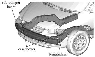
Fig. 1. Elements of the
crash control zone [4]
2. LONGITUDINALS
Longitudinals are the basic elements
in the construction of a self-supporting vehicle body. They combine several
functions. The most important of them are undoubtedly the functions of the
load-bearing element for the engine or the whole drive unit, as well as the
suspension of the front vehicle. Due to the fact that the stringers now appear
in almost every car body, and because of their shape and characteristic
location in the vehicle, they were entrusted with an additional task -
absorbing the collision energy during a car crash. As research shows, mainly
longitudinals take over the impact energy. For this reason, their role in the
aspect of passive safety of car body and whole vehicle safety is very important
(Figure 2).
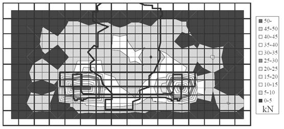
Fig. 2. The results of
measurements of the impact force of a passenger car in a rigid barrier at a
speed of about 50 km/h [5]
Longitudinals in the
self-supporting body can be treated as a remnant from times when frame
constructions prevailed.
However, the geometrical shapes of
the modern longitudinals as members of the self-supporting body do not resemble
unfinished longitudinals from frame structures made as one element. The
longitudinal of the currently produced passenger cars generally has a closed
cross-section. It is composed of at least two extrudates. In addition, a series
of additional elements may be included in the longitudinal member (Figure 3).
During the design of the
geometrical shapes of the longitudinal, the constructor may in a sense,
programme the manner and course of its deformation during the collision (Figure
4). This, of course, has an effect on the value of deformation of the body and
the value of deceleration as it affects the users of the vehicle. In order to
give the longitudinal a shape that ensures the optimal manner and course of
deformation, a series of ribs or holes were formed as geometric notches. It is
in these places that the deformation of the longitudinal will be initiated
during the impact.
An important issue regarding the
longitudinals in a self-supporting car body is the way in which they are
combined with the whole car body integrity. The method of transferring forces
from the longitudinal to the rest of the car body depends on the solution of
this construction node. In principle, it is possible to distinguish
longitudinals passing into the floor pane and longitudinals extending to the
thresholds.
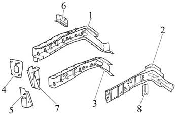
Fig. 3. Citroen C8 left
front member: 1. longitudinal member, 2. side member, 3. side member
reinforcement, 4. bracket, 5. end of the longitudinal member, 6. longitudinal
strut, 7. side member, 8. reinforcement stringer closing [6]
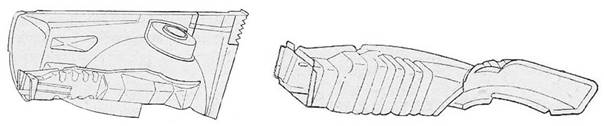
Fig. 4. Longitudinal
with a given deformation solution [7]
3. INVESTIGATION
AND RESULTS
Two types of investigations were
carried out. These are; dynamical test and computer simulation.
Dynamical test was done using a
special test stand [8÷12]. Main characteristics of the test stand for
the dynamic test are shown in Table 1. Test stand is shown in Figure 5.
Tab. 1.
Characteristics
of the test stand for the dynamic test
|
Ram mass |
to |
|
Impact velocity |
to 9.7 m/s (to |
|
Free fall height |
to 4.8 m |
|
Impact energy |
to 23.6 kJ |
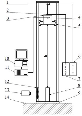
Fig. 5. Schematic
diagram of the test stand for dynamic testing of model car body elements, h –
height of free fall of the ram, 1. hoist, 2. trigger, 3. ram, 4. deceleration sensor,
5. guide rollers, 6. hoist panel, 7. trigger device, 8. model longitudinal, 9. base
of the test stand, 10. computer, 11. device for data acquisition, 12. graduation,
13. camera, 14. foundations.
Model longitudinals were done for
dynamic investigation. It consists of a few steps. In the beginning,
investigations of the real form of longitudinals were done. Examples of its
results are portrayed in Figure 6.
Next model of longitudinals was
designed. In this step, some main model features were set (shape – Figure
7, material – Table 2, joint characteristics – Tables 3 and 4). The
material used was typical steel of increased strength. The model longitudinal
was 0.5 meter long and their cross-section was close to the pair of Ω
profile. Incisions were made in the corners as deformation initiation elements.
Additionally, through holes and edge cuts were made in the walls of the model
longitudinal.
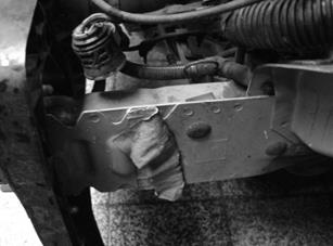
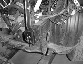
Fig. 6. Example of
observed real longitudinals of a car body
In general, spot welding was used
to connect the parts of the model longitudinal. In order to obtain the gradation
of stiffness of the model longitudinal, marginal welds at the end of it were
made. The parameters of point resistance welding are shown in Table 2, while
welding parameters in gas shields are shown in Tables 3 and 4.
Tab. 2.
The
chemical composition of the steel from which the model longitudinal were made
|
Steel grade |
Chemical composition,
% |
||||
|
S355J2G3 |
C |
Mn |
Si |
P max |
S max |
|
0.2 |
1.45 |
0.51 |
0.035 |
0.035 |
|
Tab. 3.
Parameters of point
resistance welding
|
Diameter of
electrodes, mm |
Current, kA |
The force of electrode
pressure, kN |
Welding time, s |
|
8.6 |
18.8 |
3 |
0.45 |
Tab. 4.
Metal Active Gas (MAG)
welding parameters
|
Shielding gas |
Gas flow rate, dm3/min |
The diameter of the
electrode wire, mm |
Current, A |
Voltage, V |
Wire feeding speed, m/min |
|
82% Ar + 18% CO2 |
16 |
1.2 |
150 |
25 |
11 |
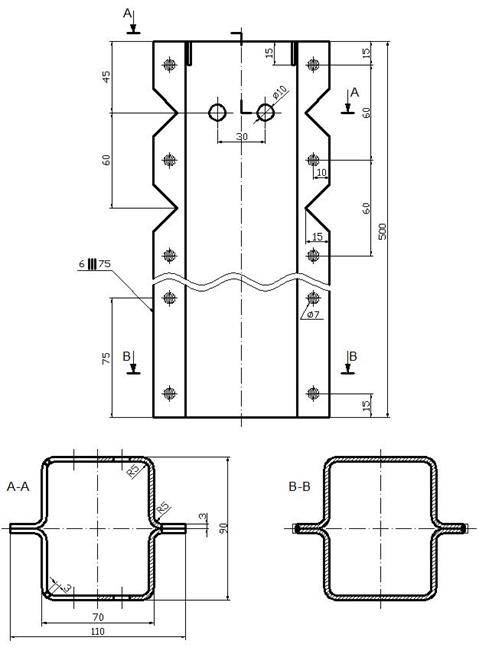
Fig. 7. Model
longitudinal
The advantages of the designed test
stand for dynamic test is that the velocity of impact can be smoothly adjusted
and free fall mass can be gradually changed. In addition, it is possible to
study model energy-absorbing elements of the car body as well as elements of
the real self-supporting car body.
According to the main assumption
regarding the method of testing, during the impact process, the deceleration of
free fall mass and the deformation of the tested element are recorded as a
function of time. Deceleration was measured by a single axis deceleration
sensor. Deformation was measured by a speed camera.
In Figure 8-11 examples of results
obtained during dynamical tests are shown. These figures illustrate the first
phase of the impact (compression). There are:
·
value of deceleration of RAM in depends on
time during impact.
·
value of velocity of RAM in depends on
time during impact.
·
value of model longitudinal deformation in
depends on time during impact.
The duration of the impact process
(first phase of the impact) was about 0.038 s. The maximum value of the
deceleration during impact was about 480 m/s2. The maximum value of the
deceleration was observed at the beginning of the impact process. It is a
characteristic feature of the time course of the deceleration during impact.
This is due to the fact that at the beginning of the impact the test piece
(model longitudinal) exhibited the highest stiffness. The time course of the
deceleration had a specific shape (characteristic changes in the parameter
value). This was due to the predetermined deformation of the model longitudinal
during the collision.
The changes in the speed of the RAM
are similar to linear. Slightly higher intensity of velocity decreasing can be
observed only at the beginning of the impact. As already mentioned, it is
caused by the stiffness of the tested element (model longitudinal) at the
beginning of the impact (initiation of deformation).
The change in the value of model
longitudinal deformation in depends on time during impact can be described as
square function. At the beginning of the impact process, the increases in the
deformation value are clearly greater than at the end of the process. This is
due to the fact that at the beginning of the impact, the RAM had great velocity
and therefore great kinetic energy. The maximum deformation value of the tested
component (model longitudinal) is approximately 88 mm.
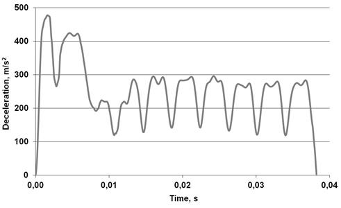
Fig. 8. Value of
deceleration of RAM in depends on time during impact (Example)
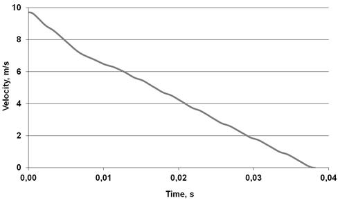
Fig. 9. Value of
velocity of RAM in depends on time during impact (Example)
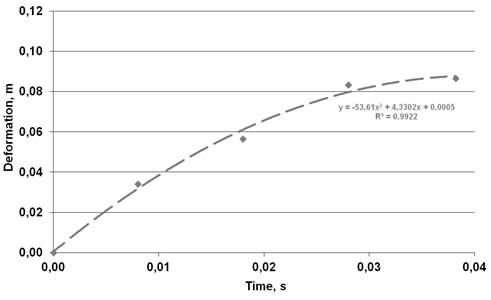
Fig. 10. Value of model
longitudinal deformation in depends on time during impact (Example)
Next part of the test was a
computer simulation. It was done using the Autodesk Simulation Mechanical 2017.
Simulations reproduce identical experimental conditions as in real samples on
model objects (model longitudinals). Examples of the results obtained during
computer simulations are presented in Figures 11 and 12.
It should be noted that the results
obtained during computer simulation are similar in value to the results of
tests on the real model longitudinal (Figures 11 and 13).
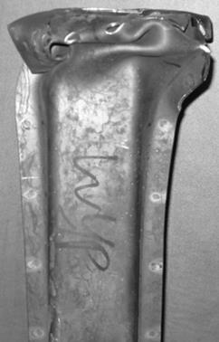
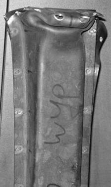
Fig. 11. Examples of
model longitudinal after tests

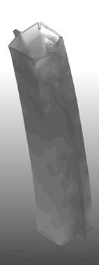
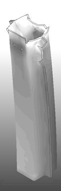
Fig. 12. Examples of
computer simulation results
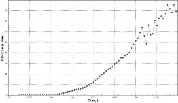
Fig. 13. Value of model
longitudinal deformation in depends on time during impact (Example of computer
simulation)
4. SUMMARY
The aim of this paper was to
present and compare the results of dynamic studies on model energy-consuming
real objects and compare the results obtained this way with the results of
computer simulation within the same range.
For investigation simplified test
stand was designed and constructed (experimental research stand). Moreover, a
computer simulation was done for similar conditions.
On the basis of this investigation,
it is possible to conclude that:
· passive safety of the
car body is a very important subject.
· longitudinal is the
component which absorbed a lot of impact energy.
· it is possible to carry
out crash tests on individual components of the car body (instead of the whole
car).
· the time course of the
impact deceleration has a characteristic shape (high values at the beginning of
the process and subsequent variations of the parameter value).
· it is possible to carry
out a computer simulation of the impact process, and the results obtained there
are comparable to those on real objects (values of parameters).
References
1.
Romaniszyn K.M. 2006. „Wpływ struktury przodu nadwozia
na energochłonność”. [In Polish: „The influence of the structure
of the front of a car chassis on its energy dissipation”]. Zeszyty Naukowe Politechniki
Świętokrzyskiej, Mechanika z. 84: 287-292.
2.
Baranowski P.,
R. Burdzik,
J. Piwnik. 2011. „Measure and analysis of crash
vehicle deformation”. Aparatura Badawcza
i Dydaktyczna 16(1): 11-16.
3.
Gill A. 2001. „Ocena skuteczności działania
elementów bezpieczeństwa biernego samochodów osobowych na
podstawie wyników badań zderzeniowych”. [In Polish: “Efficiency assessment
of passive safety elements in passengers cars on the base of crash tests
results”]. Zeszyty Naukowe Politechniki
Poznańskiej, Maszyny Robocze i Transport 53: 117-123.
4.
TopSpeed.
Available at: http://www.topspeed.com/cars.
5.
Arai Y., K. Yamazaki, K. Mizuno, H. Kubota. „Full-width tests to evaluate
structural interaction”. 20th International Technical
Conference on the Enhanced Safety of Vehicles (ESV). Lyon , France, 2007-6-18
to 2007-6-21. Paper Number 07-0195.
6.
Technical
data and training materials of Citroen, Model C8, PSA 2006.
7.
Kobus W. 1987. Nowe metody
napraw nadwozi samochodów osobowych. [In Polish: New
methods for repairing passenger car bodywork]. WKił:
Warsow.
8.
Song H.W., Z.M. Wan, Z.M. Xie, X.W. Du. 2000. “Axial impact behavior and energy
absorption efficiency of composite wrapped metal tubes”. International Journal of Impact Engineering
24(4): 385-401.
9.
Juntikka
R., S. Hallstrom. 2004. „Weight-balanced drop test method for
characterization of dynamic propertiesof cellular materials”. International Journal of Impact Engineering
30(5): 541-554.
10. Peroni L., M. Avalle, G. Belingardi. 2008.
„Comparison of the energy absorption capability of crash boxes assembled
by spot-weld and continuous joining techniques”. International Journal of Impact Engineering 36(3): 498-511.
11. Tobota
A., J. Karliński, A. Kopczyński. 2007. „Axial crushing of monotubal and bitubal
circular foam-filled sections”. Journal
of Achievements in Materials and Manufacturing Engineering 22(2): 71-74.
12.
Dahil
L. 2017. “Effect on the vibration of the suspension system”. Metalurgija
56(3-4): 375-378.
Received 12.11.2018; accepted in revised form 11.01.2019
![]()
Scientific
Journal of Silesian University of Technology. Series Transport is licensed
under a Creative Commons Attribution 4.0 International License