Article citation information:
Zioła, A. Verification of road accident simulation created with the use of PC-Crash software. Scientific Journal of Silesian University of Technology. Series Transport. 2018, 98, 211-221. ISSN: 0209-3324. DOI: https://doi.org/10.20858/sjsutst.2018.98.20.
Artur ZIOŁA[1]
VERIFICATION
OF ROAD ACCIDENT SIMULATION CREATED WITH THE USE OF PC-CRASH SOFTWARE
Summary. The paper discusses an example of PC-Crash software usage for road accident reconstruction. Only a segment of the software capabilities is presented, together with a comparison of the visualized 3D simulation with the actual collision video record.
Keywords: PC-Crash, road accident reconstruction, road accident visualization, vehicles collision
1. INTRODUCTION
Traffic is inseparably connected to
road accidents. The amount of road accidents per million citizens and the
related mortality rates in Poland are among the highest in the EU. There is an
obvious need to carry out any possible actions that may lead to a decrease in
these numbers. The effectiveness of these actions depends, for example, on the
adequate assessment of collision reasons.
The appropriate assessment of
accident causes is vastly important in terms of determining criminal
responsibility and damage compensation.
This paper presents a comparison
between a simulation of a road accident based on trails left at the scene, as
prepared by the author using PC-Crash software, and the actual course of a
crash recorded by a car video recorder placed in a motor vehicle not involved
in the respective accident (the recording vehicle was moving behind one of the
colliding vehicles).
2. ROAD ACCIDENT RECONSTRUCTION
The main task of reconstruction is to recreate the course of an accident
in order to recognize the causes of a crash. First of all, one must conclude
and calculate the vectors and values of velocity affecting the colliding
vehicles. These conclusions can be made based on simulations and
reconstructions.
Impact simulation depends on appropriately calculating the parameters
characterizing vehicle movement in the first moment after impact. These
mathematical operations are based on data describing the moment just before
impact.
Reconstruction is an inversion of simulation. One can say that, during
simulation, time runs forward, as opposed to reconstruction, where time goes
backward.
The vectors and values of velocity at the start of collision can be
determined, based on calculations derived from the law of momentum:
![]() (1)
(1)
![]() (2)
(2)
![]() sin(α2-α1)
≠ 0,
sin(α2-α1)
≠ 0,
or based on calculations derived from the law of
angular momentum:
![]()
![]() (3)
(3)
![]() (4)
(4)
where V1, V2
are the values of velocity at the start of collision; V’1, V’2 are the values of velocity at the
start of post-collision movement; m1,
m2 represent the mass of the vehicles; α represents the angle of velocity vectors; Sx
is the impulse component in the ‘x’ direction of the accepted coordinates
system; Sy is the impulse component in the ‘y’ direction of the
accepted coordinates system; Δω1, Δω2 represent
the gain of angular velocity caused by the accident [1/s]; Jc is the moment of vehicle inertia in
relation to the vertical axis pierced by the vehicle’s centre of mass; and xc, yc are the centres
of the mass coordinates in relation to ‘z’.
The values of velocity at the
start of the post-collision movement are as follows:
![]() , (5)
, (5)
![]() . (6)
. (6)
The values of velocity at the
start of collision are as follows:
![]() (7)
(7)
![]() (8)
(8)
There is a number of simplified models that allow us to calculate the
linear and angular velocity of a vehicle at the start of its slipping movement.
These models can be used until the movement distance of the centre of mass and
the variations in the longitudinal axis rotation angle are known during the
whole motion.
The Marquard model is an example of these above-mentioned simplified
models. It was created for two-wheel vehicles, in which adequate coefficients
are set by averaging the calculation results in relation to the time of the
motion. These coefficients allow us to perform a reconstruction based on
simplified formulas with reasonably good approximation, based on the law of
kinetic energy and work balance.
For this study, estimating post-collision movement parameters is based
on the Marquard model (full slide movement):
![]() (9)
(9)
![]() (10)
(10)
![]()
![]()
![]()
where Vc’
represents the values of linear velocity in the centre of mass at the start of
the post-collision movement [m/s]; ω’
is the angular velocity value at the end of the impact [1/s]; μs is the slide
traction coefficient; S is the length
of the mass centre movement [m]; Vk
represents the values of linear velocity in the centre of mass at the end
of the post-collision movement [m/s]; g is
the gravitational constant; L is the axis gauge [m]; ic is the vehicle’s inertia
radius [m]; Δφ is the total
rotation angle in the post-collision movement [rad]; and
ks, kφ are Marquard’s
coefficients.
The Marquard model allows us
to estimate the velocity at the beginning of the post-collision movement. It
can be used in a situation when all wheels are blocked or no wheel can roll. In
reality, one will often confront the situation where only one or some of the
wheels will be blocked (e.g., as the cause of post-impact structural damage or
deformities).
The Burgard model [1] allows us to
calculate a vehicle’s movement parameters at the moment just after the end of
the impact by considering the impulse vector direction and the breaking force depending
on the wheel damage.
The value of the linear and angular
velocities in the centre of mass at the start of the post-collision movement
can be calculated with the use of the following:
![]() (11)
(11)
![]() (12)
(12)
although: ![]()
(a’ represents the effective delay of the post-collision movement)
where Vp’
represents the values of linear velocity in the centre of mass at the start of
the post-collision movement [m/s]; ωp’
is the angular velocity value at the end of the impact [1/s]; μs is the coefficient
of slide traction; S is the length of
the mass centre movement [m]; Vk
represents the values of linear velocity in the centre of mass at the end
of the post-collision movement [m/s]; m is
the mass of the vehicle [kg]; g is
the gravitational constant; fh is
the breaking force partition coefficient, whose value includes the amount of
force and the nature of the braking by the wheels; ωr is the rotation resistance
coefficient; l is the axis gauge [m];
Jc is the moment of
vehicle inertia in relation to the vertical axis, pierced by the vehicle’s
centre of mass [kgm2]; and
Δφ is the total rotation
angle in the post-collision movement [rad].
In the case of unblocked front wheels, their
angle of rotation from the longitudinal position may be essential. The precise
analysis of such a case can only by conducted by calculating the configuration
of unilinear derived functions of movement. Such analysis allows us to conduct
post-collision movement parameters by considering geometrical changes of the
vehicle, especially, the wheels’ dislocation caused by deformations.
3. PC-CRASH SOFTWARE
FOR RECONSTRUCTION CALCULATIONS
Currently, a wide variety of software
is available for use in reconstructing vehicle crashes and the dynamics of
movement calculations on a broad scale, such as PC-Crash, V-SIM, VirtualCRASH, CARAT and HVE [3]. One of the most popular
in Poland is PC-Crash (DSD PhD Steffan Datentechnik, Austria).
PC-Crash
software has been designed for carrying out mathematical calculations for the
purpose of reconstructing road accidents. The software allows us to simulate
the course of action in almost all eventualities, due to the integration of numerous
modules, in particular, vehicle databases, vehicles’ dynamic models, crashes
and multichunk arrangements, graphic modules and 3D animation sequences. It
specifically enables the simulation of movement and collision between two
vehicles (e.g., single- or double-track vehicles), and between vehicles and
environmental objects (e.g., trees, walls), foundations (e.g., when a vehicle
turns around, debris falling from scarps or trenches), and biomechanical
objects (e.g., pedestrians, passenger movements). The software also facilitates
time and space analysis of accident, which is essential for assessing the
correctitude of participants; actions in the moments before an event.
PC-Crash
allow us to simulate the course of action in general case, from the beginnings
of endangerment through the pre-collision, collision and post-collision
movements until the movement arrest. The software provides three accident models:
-
Kudlich-Slibar (classic or Newtonian)
-
Rigidness, using multichunk arrangements modelling
- Reticular,
external coating, represented by a deforming net
Simulation
is the base method of analysis. The Kudlich-Slibar model is used for simulation
in which the post-collision vehicle’s movement parameters are calculated, based
on data from the moment before impact. The model assumes that collision time is
infinitesimal, which is why vehicle movement during impact is neglected. An
impact vector is placed in one particular spot and all other external forces
(e.g., influence of the road on wheels) are disregarded [4].
4. CASE STUDY
This chapter presents a fact-based
crash reconstruction with the use of the Kudlich-Slibar model and PC-Crash
software. Data used in this case are taken from court files relating to a
particular road accident.
A Seat Leon driver attempted to
perform an overtaking manoeuvre in relation to multiple vehicles; however, this
individual did not pay regard to the horizontal P-3 traffic sign (unilateral
non-transgressing line). During the motion on the lane in the opposite
direction, the vehicle collided frontally with a VW Golf III passenger car. At
the time of the crash, the Seat Leon was placed beneath a hill peak and in
front of a road bend.
The
evidence left at the scene is indicated on Figure 1.
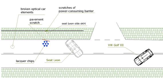
Fig. 1.
Scene sketch
The evidence
from both vehicles indicates that three events occurred at the time of the
accident:
1.
Frontal collision between the Seat Leon
and the VW Golf III
2.
Collision between the Seat Leon’s left-posterior corner and the
power-consuming barrier
3.
Collision between the VW Golf’s left-posterior bumper corner and a third
car at the level of the posterior-left wheelhouse shell
During the
latter impact, the VW Golf’s stern could have been lifted by around 0.5 m
(Figure 3), with the third vehicle moving in the opposite lane in the
appropriate direction.
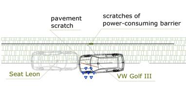
Fig. 2. The placement of the Seat
Leon and the VW Golf III at the time of frontal impact
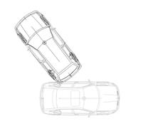
Fig. 3. Relative placement of the VW Golf III and the
third vehicle (moving in the opposite lane) at the time of impact
During the
impacts, the vehicles sustained significant deformations (the computer software
provides the option to modify the geometry of the models). Those modifications
are included in the calculations of the post-impact movements (Figures 4-5).

a b
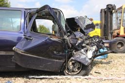
Fig. 4. The Seat Leon’s geometry
shift caused by deformation: a) fact-based photograph of the scene; b) model
used in the post-impact movement calculations
a b
Fig. 5. The VW Golf’s geometry shift
caused by deformation: a) fact-based photograph of the scene; b) model used in
the post-impact movement calculations
During the
initial simulations, difficulties with accurately recreating the VW Golf’s
second impact involving the left-posterior bumper corner occurred, i.e., during
the initial simulation, the car rear could not be lifted into the appropriate
position. The vehicle that took part in the accident was heavily used. There is
a probability that the rear-axis shock absorbers were not working as intended.
The PC-Crash software allows the user to define the suspension parameters:
after lowering the damping ratio of the rear-axis shock absorbers, the expert
witness applied the simulated course, which justified the revealed evidence.
Carrying
out these simulations allowed us to calculate the probable crash velocities: VW
Golf – 40.0-45.0 km/h; Seat Leon – 83.0-89.0 km/h. The lowest error value of
6.2% (weighted relative error) [4, 7] was determined for the
velocities for the VW Golf at 41.0 km/h and the Seat Leon at 85.0 km/h.
Being able
to create a 3D animated video of the accident, based on mathematical
calculation results, is an essential software requirement. A video of this kind
is particularly useful for the accurate evaluation by specialists in other
disciples (e.g., lawyers).
The course
of this accident was recorded by video camera in one of the cars in the column
overtaken by the Seat Leon.
The
figures below present a comparison of the real crash video and the 3D animation
of the discussed collision at the time of the accidence (Figures 6-8).
a
b
Fig. 6. Frontal crash involving the
Seat Leon and the VW Golf: a) film frame from the car video recorder; b) 3D
view from the simulation
a
b
Fig. 7. Collision of the Seat Leon’s left-posterior corner with the
power-consuming barrier: a) film frame from the car video recorder; b)
3D view from the simulation
a
b
Fig. 8.
Collision of the VW Golf’s left-posterior bumper corner with the third car,
which was moving in the opposite lane in the appropriate direction: a) film frame from the car video
recorder, b) 3D view from the simulation
5. CONCLUSIONS
Increasingly complex simulation
software is available, which allows for the course of accidents to be
recreated, as well as the presentation of results following the arduous and
complicated calculation of relevant parameters [5,6]. In the discussed case,
the author refers to PC-Crash. An additional option provided by this software is
the ability to present the accident as a short, animated movie, which can
accurately reflect the real accident.
Progress made in the area of
personal computers has enabled programmers to provide increasingly complex
calculation algorithms, together with other advanced tools involving, for
example, the finite element method and software used by expert witnesses [11,12,13].
Additionally, the actual progress of
artificial intelligence (AI) developments has meant that simulation software is
more commonly used for complex calculations. Its broad use can be observed,
including indirectly in the courts during cases that require the reconstruction
of road accidents.
The literature presents many
approaches to solving problems in the context of analysing images with AI [14-17].
The authors of AI-related papers have paid particular attention to the analysis
of the sensitivity of relevant models [18,19].
On the topic of road accidents, it
is noteworthy that a considerable amount of research has taken place on road
safety around the world, in which authors has focused on both human and
technical aspects in relation to the occurrence and course of road accidents
[3,20-22]. One needs to remember that a road accident is always the effect of
various factors, such as human, vehicle or environmental factors. It is also
important to bear in mind the numerous studies that have led to improvements in
the reliability of vehicle elements and their proper diagnostics [23-35].
We hope that, as a result of ongoing
technological progress, the increased accessibility of advanced algorithms and
relevant international studies will lead to a decrease in the number of road
accidents and improvements in their outcomes, or at least allow for their real
course of action and causes to be established at an easier stage.
References
1.
EVU
Unfallrekonstruktions-Programme, Bediengungshaandbuch, Auslauf – Analyse
rückwärts. EVU, Wiesbaden 1991.
2.
Marquard E. 1968.
“Fortschritte in der Berechnung von Fahrzeung-Zusammenstössen”. ATZ 3.
3.
Institute of
Forensic Research. 2011. Road Accidents.
Guidelines for Expert Witnesses. Cracow: Institute of Forensic Research
Publishers. ISBN 83-87425-32-X
4.
Wach Wojciech.
2009. Road Accidents Simulation with
PC-Crash Software. Cracow: Institute of Forensic Research Publishers. ISBN
83-87425-23-0.
5.
Wach Wojciech.
2014. Structural Creditability of Road
Accidents Reconstructions. Cracow: Institute of Forensic Research
Publishers. ISBN 83-87427-14-1.
6.
Wach Wojciech.
2009. “Reliability in establishing road accident cause”. Paragraf na drodze (Special Edition): 115-133. ISSN 1501-3520.
7.
Wach Wojciech.
2011. “Verification of vehicle collision simulation in respect of modelling
uncertainty”. Paragraf na drodze 2:
43-63. ISSN 1505-3520.
8.
Zębala Jakub,
Wojciech Wach, Piotr Ciępka, Robert Janczur, Stanisław Walczak. 2009.
“Verification of ABS models applied in computer program PC-CRASH”. Paragraf na drodze (Special Edition):
151-171. ISSN 1501-3520.
9.
Zębala Jakub,
Wojciech Wach, Piotr Ciępka, Robert Janczur,. 2013. “Simulation in PC-CRASH
program of car motion with reduced tyre pressure”. Paragraf na drodze (Special Edition): 309-323. ISSN 1505-3520.
10.
Zębala Jakub.
2017. “Simulation, in the PC-CRASH program, of movement of a car with no tire
pressure in one rear wheel”. Paragraf na
drodze (Special Edition):
337-346. ISSN 1505-3520.
11.
Wittek
Adam Marek, Damian Gąska, Bogusław Łazarz, Tomasz Matyja. 2014. “Automotive
stabilizer bar – stabilizer bar strength calculations using FEM, ovalization of
radial areas of tubular stabilizer bars”.
Mechanika 20(6): 535-542. ISSN 1392-1207.
12.
Gąska
Damian, Tomasz Haniszewski, Jerzy Margielewicz. 2017. “I-beam girders
dimensioning with numerical modelling of local stresses in wheel-supporting
flanges”. Mechanika 23(3): 347-352.
ISSN 1392-1207.
13.
Gąska
Damian, Czesław Pypno. 2011. “Strength and elastic stability of cranes in
aspect of new and old design standards”. Mechanika 17(3): 226-231. ISSN
1392-1207.
14.
Ogiela Lidia,
Ryszard Tadeusiewicz, Marek Ogiela. 2006. “Cognitive analysis in diagnostic
DSS-type IT systems”. In Proceedings of
the Eighth International Conference on Artificial Intelligence and Soft
Computing (ICAISC 2006). Zakopane, Poland. 25-29 June 2006. Book Series: Lecture Notes in Computer Science Vol. 4029: 962-971.
15.
Ogiela Lidia,
Ryszard Tadeusiewicz, Marek Ogiela. 2006. “Cognitive computing in intelligent
medical pattern recognition systems”. In D.S. Huang, K. Li, G. Irwin, eds., International Conference on Intelligent
Computing: Intelligent Control and Automation. Kunming, China. 16-19 August
2006. Book Series: Lecture Notes in
Control and Information Sciences Vol. 344: 851-856.
16.
Ogiela Marek, Ryszard
Tadeusiewicz, Lidia Ogiela. 2005. “Intelligent semantic information retrieval
in medical pattern cognitive analysis”. In O. Gervasi, M.L. Gavrilova, V. Kumar
et al., eds., Proceedings of the
International Conference on Computational Science and Its Applications (ICCSA
2005): Vol. 4. Singapore. 9-12
May 2005. Book Series: Lecture Notes in Computer Science Vol. 3483:
852-857.
17.
Tadeusiewicz
Ryszard, Lidia Ogiela, Marek Ogiela. 2008. “The automatic understanding
approach to systems analysis and design”. International
Journal of Information Management 28(1): 38-48.
18.
Smyczyńska U., J. Smyczyńska, M. Hilczer, R. Stawerska, R. Tadeusiewicz, A. Lewiński. 2018. “Pre-treatment growth and IGF-I deficiency as
main predictors of response to growth hormone therapy in neural models”. Endocrine Connections 7(1): 239-249. DOI: 10.1530/EC-17-0277.
19.
Tadeusiewicz
Ryszard. 2015. “Neural networks in mining sciences – general overview and some
representative examples”. Archives of
Mining Sciences 60(4): 971-984. DOI: 10.1515/amsc-2015-0064.
20.
Czech Piotr. 2017.
“Physically disabled pedestrians – road users in terms of road accidents”. In
E. Macioszek, G. Sierpiński, eds., Contemporary
Challenges of Transport Systems and Traffic Engineering. Lecture Notes in
Network Systems Vol. 2: 157-165.
Cham, Switzerland: Springer. ISSN: 2367-3370. DOI:
https://doi.org/10.1007/978-3-319-43985-3_14.
21.
Czech Piotr. 2017.
“Underage pedestrian road users in terms of road accidents”. In
G. Sierpiński, ed., Intelligent
Transport Systems and Travel Behaviour. Advances in Intelligent Systems and
Computing Vol. 505: 75-85. Cham Switzerland: Springer. ISSN: 2194-5357.
DOI: https://doi.org/10.1007/978-3-319-43991-4_4.
22.
Yannis G., P. Papantoniou, M. Nikas 2017. “Comparing young drivers speeding behavior at rural areas in
normal and simulation conditions”. Transport\Transporti
Europei 66(4)5: 1-13. ISSN: 1825-3997.
23.
Bigoš P., J.
Kuľka, M. Mantič, M. Kopas. 2015. “Comparison of local stress values obtained
by two measuring methods on blast furnace shell”. Metalurgija 54(1): 101-104.
24.
Czech P., Mikulski
J. 2014. “Application of Bayes Classifier and Entropy of Vibration Signals to
Diagnose Damage of Head Gasket in Internal Combustion Engine of a Car”. Telematics - Support For Transport.
Communications in Computer and Information Science 471: 225-232.
25.
Grega R., J.
Homisin, M. Puskar, J. KuI’ka, J. Petroci, B. Konecny, B. Krsak. 2015. “The
chances for reduction of vibrations in mechanical. System with low-emission
ships combustion engines”. International
Journal of Maritime Engineering 157(A4): 235-240. DOI:
10.3940/rina.ijme.2015.a4.335.
26.
Harachová D. 2016 “Deformation
of the elastic wheel harmonic gearing and its effect on toothing”. Grant Journal Vol. 5, No. 1: 89-92,
ISSN: 1805-0638.
27.
Homišin J.,
P. Kaššay, M. Puškár, R. Grega, J. Krajňák, M. Urbanský, M. Moravič. 2016.
“Continuous tuning of ship propulsion system by means of pneumatic tuner of
torsional oscillation”. International
Journal of Maritime Engineering: Transactions of the Royal Institution of Naval
Architects 158(A3): 231-238. ISSN: 1479-8751. DOI:
10.3940/rina.ijme.2016.a3.378.
28.
Krajnák J.,
J. Homišin, R. Grega, M. Urbanský. 2016. “The analysis of the impact of
vibrations on noisiness of the mechanical system”. Diagnostyka 17(3): 21-26.
29.
Kulka J., E.
Faltinová, M. Kopas, M. Mantič. 2016. “Diagnostics and optimisation of crane
track durability in metallurgical plant”. Diagnostyka
17(3): 41-46.
30.
Medvecká-Beňová
S. L. Miková, P. Kaššay. 2015. “Material properties of rubber-cord flexible
element of pneumatic flexible coupling”. Metalurgija
54(1): 194-196.
31.
Puskar Michal,
Michal Fabian, Jaroslava Kadarova, Peter Blist’an, Melichar Kopas. 2017.
“Autonomous vehicle with internal combustion drive based on the homogeneous
charge compression ignition technology”. International
Journal of Advanced Robotic Systems 14(5). DOI: 10.1177/1729881417736896.
32.
Puskar Michal,
Melichar Kopas, Jaroslava Kadarova. 2017. “Ecological analysis related to
creation of gaseous emissions within transport focused on fulfilment of the
future emission standards”. Transportation
Research Part D: Transport and Environment 57: 413-421. DOI:
10.1016/j.trd.2017.10.007.
33.
Vojtková
Jarmila. 2016. “Benefits of application of spur gears with asymmetric profile”.
Pomiary Automatyka Robotyka 2(20):
31-35. DOI: 10.14313/PAR_220/31.
34.
Zelić A., N.
Zuber, R. Šostakov. 2018. “Experimental determination of lateral forces caused by
bridge crane skewing during travelling”. Eksploatacja
i Niezawodnosc – Maintenance and Reliability 20(1): 90-99. DOI:
http://dx.doi.org/10.17531/ein.2018.1.12. ISSN: 1507-2711.
35.
Zuber N., R.
Bajrić. “Application of artificial neural networks and principal component
analysis on vibration signals for automated fault classification of roller
element bearings”. Eksploatacja i
Niezawodność - Maintenance and Reliability 18(2): 299-306. DOI:
10.17531/ein.2016.2.19. ISSN: 1507-2711.
Received 02.11.2017; accepted in revised form 20.01.2018
![]()
Scientific Journal of
Silesian University of Technology. Series Transport is licensed under
a Creative Commons Attribution 4.0 International License