Article citation information:
Redo, W. Selected aspects of the quality of parameter measurements saved by on-board recorders. Scientific Journal of Silesian University of Technology. Series Transport. 2018, 98, 119-131. ISSN: 0209-3324. DOI: https://doi.org/10.20858/sjsutst.2018.98.12.
Wojciech REDO[1]
SELECTED
ASPECTS OF THE QUALITY OF PARAMETER MEASUREMENTS SAVED BY ON-BOARD RECORDERS
Summary. This article highlights the specifics of on-board recorders among the various systems found on aircraft. Attention is drawn to the legal and technical compliance requirements concerning modern on-board recorders. Reference is also made to certain aspects of recording methods and data security. Furthermore, the paper especially focuses on the process of measuring a parameter, indicating the basic criteria regarding the accuracy of the measurement. In addition, the role of two essential elements in the measuring chain is discussed: the feeder as a parameter measurer and the transformation system, i.e., AC converter.
Keywords: flight data recorder, registration system, feeder, accuracy of parameter measurement
1. INTRODUCTION
On-board flight recorders belong to a group of devices
of aircraft equipment that are subject to stringent requirements. The
specificity of these devices stems from their destination and purpose for which
they are built on aircraft, compared with how other aircraft systems
operationalize these functions. The basic functions of on-board recorders
involve recording significant operating parameters of systems and on-board
installations of the aircraft, as well as the parameters of the spatial
position and their memorization and protection.
Today’s on-board recorders are technologically advanced devices in terms of
design and data processing. In practice, on-board recorders are used to record
up to a hundred different types of parameters. As such, the number of currently
registered parameters is no longer problematic; but, accuracy remains an issue,
from the time of measuring the parameter values, through all the phases of
conversion and encoding, to the restoration of their physical values in the
registered entries.
2. DIVISION AND THE STANDARDS FOR ON-BOARD
RECORDERS
Considering the types of data recorded by
on-board recorders, four main groups of recorders can be identified:
1.
Flight data recorders (FDRs)
2.
Recorders of conversations and sounds in the cockpit, i.e., cockpit voice
recorders (CVRs)
3.
Recorders of board images, i.e., airborne image recorders (AIRs)
4.
Recorders of digital data links, i.e., data link recorders (DLRs)
The first
two types may exist either as two separate
devices or as single integrated units. Registration systems for the flight are
now standard equipment on all civilian and state aircraft. These systems should
not be equated with other aircraft systems, as they play quite a different
role. The distinguishing feature of such systems is that they play out the role
of “controller” concerning the given airship
parameters and database for the course of the flight. Thus, bearing in mind the
specificity of the system, there is an obvious need to meet the requirements
set by them. It should be mentioned that all formal and legal issues (including
the requirements) regarding the operation of civil aviation is governed by the International
Civil Aviation Organization (ICAO), established under the Convention on
International Civil Aviation (also known as the Chicago Convention), which is
an international agreement regulating issues in the field of aviation law,
signed in Chicago on 7 December 1944.
Detailed requirements on recording
equipment are included in Annex 6 to the Chicago Convention [1], which covers
the operation of aircraft. These requirements mainly concern:
–
The definition of recorder working time (in relation to the readiness to turn
off)
–
Parameters that must be registered
–
Types of recorders and systems of flight data recording
–
Construction and assembly
Meanwhile, detailed expectations for
military aviation recording equipment are found in Decision No. NO-16-A200
entitled the “Defensive Standard on Military Aircraft: On-board Catastrophic
Recorders – Requirements and Tests”[2].
The standard specifies the
requirements and functional characteristics of on-board catastrophic recorders
installed on military aircraft, as well as include a list of recorded
parameters and test methods concerning the impact resistance of recorders in
relation to factors present at the time of the crash of the aircraft. The
standard also defines the specifications of flight data and disposable signals
recorded by on-board catastrophic recorders on military aircraft and a list of
authorized uses for certain types of sensors that measure parameters found on
multi-engine airplanes (transport), fighters, attack aircraft, trainer aircraft,
helicopters and airplanes capable of vertical or short take-offs and landings
[6].
Given the above requirements and the previously
mentioned features of the registration system, one should not relate its
functionality to the role of the autonomous recorder. This is because an
on-board recorder system realizes not only the parameter registration process,
but also the measurement of parameters and their transformations. Modern
registration systems for flights charge selected data from on-board databases
and specialized sensors (feeders). Thus, by understanding the organization of
the processes carried out by different types of recorders, one can define the
purpose of registration systems as systems for recording and protecting
specific groups of data:
1.
Parameters of the flight
2. The
parameters of the powertrain
3.
Location of aircraft controls
4.
Status of individual devices and installations
There is also a need to assess:
1.
Flight safety
2.
Techniques of piloting,
3.
Technical state of the exploited aircraft
In other words, as a “record”, we refer to an
ordered stream of change (ARINC code) in the data (events) as a function of
time. In turn, the “protection” of the recording is realized through the
technical protection of data collected by the recording element, located in the
construction (casing) line of the catastrophic recorder, against the
effects of exceptionally extreme
external factors.
Given the aviation tasks, maintenance as well
as cases of unforeseen air events, it is necessary to adjust the recorder
design for quick access to stored data. This type of requirement is provided by
the practical application of the on-board recorder for wireless data
transmission, mobile operating cartridges or other storage media (e.g., in line
with Personal Computer Memory Card
International Association standards). Portable cassette supplies are
often referred to as quick access recorders (QARs). A QAR is used as a double
of a catastrophic recorder and contains the same recording data as a
catastrophic recorder. For the catastrophic recorder system, there is an
opportunity to join up with a portable QAR. Such an option involves BUR and
TESTER recorders.
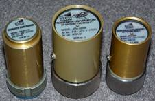
Figure 1 shows two types of QAR produced by
ATM. The ATM-QR4 recorder was the successor of the unproduced
ATM-QAR and came into production in 1996. Compared to the previous model, all
the technical parameters were improved, so that it was possible to use modern
memory cassettes in the MC5 series with a large capacity. The only elements
that did not change were the external dimensions and the connector connecting
the recorder with the on-board installation of the aircraft, meaning that
interchangeability was retained with the old model. An important solution by
which the QAR differed from the QR4 concerned the modular design, which allowed
the configuration of the recorder to change, even during operations [8].
|
|
|
|
Fig. 1. Quick access recorders: ATM-QAR and
ATM-QR4 Source: WSOSP LKL; ATM |
|
However, for the security of recorded data,
safety record cassettes are used to protect the data on the permanent memories
(flash), magnetic media and photosensitive materials. Building the safety
cassette system (catastrophic) into the rear part of the fuselage increases the
chances for users to save data under the most extreme conditions. It should be
added that the structure of the same catastrophic cartridge and its
functionality must meet the requirements of the NO-16-A200 standard. Currently
used recorders must have the capacity for saving:
–
2 h of flight information in the case of CVRs
–
25 h of flight information in the case of FDRs
The number of recorded analogue and discrete
parameters depends on the type of aircraft and can reaches up to 1,000.
Catastrophic recorders have to survive a crash,
which means there are certain minimum criteria to be met by protective tape in
order to for undamaged records to be recovered. The main criteria are:
– Immersion in consumables liquids (aviation fuel,
oils, hydraulic fluid) for 48 h
– Hydrostatic pressure of seawater at a depth of 6,000
m for 30 days,
– Testing of fire temperature to 1,100°C for 30 min
– “Oven” testing at a temperature of 260°C for 10 h
– G-force overload to 3,400 units with a duration of
6.5 ms
– Direct impact of 226 kg of weight falling from a
height of 3 m onto the surface of the protective cartridge, along with a
ball-shaped blade with a diameter of 6 mm
Underwater locator beacons are built into
today’s protective cassettes systems, which act as transmitters sending signals
to confirm their location (time to send a signal: up to 30 days). The
protective cassettes are installed as sources of electricity (batteries) used
to maintain the contents of flash memory for up to 10 years.
For the above-described design solutions for
on-board recorders, collected data can be stored on two types of cassettes,
which differ in terms of their ability to survive under extreme conditions:
namely, operational cassettes (in QARs) and catastrophic cassettes. A flight
data recorder stores the same information on a protective cartridge or a quick
access cartridge (operational).
Data stored on a protective cartridge are used
to analyse the causes of air events, while data from a quick access cassette
are mainly used for the analysis of the mission carried out by the crew of the
aircraft.
To summarize, a flight data recorder is
generally designed for recording analogue signals, digital signals, and
frequency and disposable (binary) signals originating from feeders and onboard
equipment on cassettes, as well as identification data entered by the crew
before the flight or automatically.
|
|
|
|
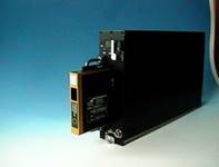
Fig. 2. Installation of an S23ai
recorder on Source: LKL WSOSP |
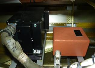
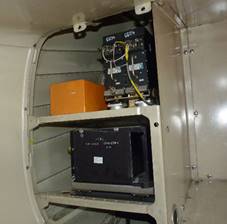
Fig. 3. Installation of an S23A
recorder on an SW-4 Source: LKL WSOSP |
3. MEASUREMENT OF PARAMETERS
3.1. Sources of
information
As
mentioned above, the operation of all aircraft systems and, in principle, the
operation of each on-board device are not technical problems concerning how to
register the status represented by a parameter or a specific group of
parameters. Ensuring the proper functionality of recorders comes down to:
– Defining the scope (number) of measured and recorded
parameters
– Determining the type and extent of the measured
parameter
– Selecting the appropriate kind (type) of feeder
(transducer)
– Correcting (according to technical guidelines and
the laws of physics) the installation of the feeder (transducer) on board the
aircraft (design requirements)
– Executing (according to technical guidelines) the
recorder connection
– Scaling the measuring channels (feeders)
– Checking the proper operation during the flight
Defining the element that directly measures a
parameter with the word czujnik (sensor) is mainly due to the fact that this element is referred
to in English as “sensor”. However, mainly because of the many years of
operation in domestic aviation involving Russian-produced recorders, it is
defined within the context of technical nomenclature by the word
“датчик”, which literally means feeder
(giver, provider or
supplier). Defining the element for
measuring the feeder clearly reflects the meaning of the principle of operation
of this element: to measure the parameter and pass the information, in this
case, to the on-board recorder. This qualification implemented by the function
of this element basically requires it to be
called a transmitter. When determining the measuring element as a czujnik
or sensor in the future, the property
of “passing on” should also be borne in mind, which means we can then use these
terms interchangeably: feeder and transmitter.
The system of collecting information
about the status of the aircraft is based on data obtained
from a specific location (the system) of aircraft by using a sensor (feeder)
that can adequately measure the parameter. While sensors are deployed in
different parts of the aircraft, they are mostly located in points that have a
critical impact on the course of all phases of the flight (propulsion,
hydraulic, control, chassis system etc.). Their number depends on the size of
the aircraft structure, the drive type and the destination. Furthermore, they
simply communicate all data to a collective information unit (or
flight data acquisition unit), which acts as their “eyes and ears”.

Fig. 4. Sources of information and
types of recorded signals
3.2. Classification of
measuring sensors
Concerning today’s on-board
recorders, we have to deal with different types of feeders
used by manufacturers. In terms of the number of recorded parameters and their
individual types (analogue, digital, frequency, single), analogue parameters
constitute the vast majority. A sample juxtaposition
of recorded parameters of the aircraft with respect to the type of feeder is presented in Table 1.
Tabl. 1
Examples of feeders for measuring
parameters (variant)
|
Parameter name |
Type of feeder |
Kind of feeder |
|
Airspeed |
MDD-Tje-0-1,5 |
A |
|
Amount
of barometers |
MDD
Tje-1-780 |
A |
|
Rudder
angle |
MU-614 |
A |
|
DSS
position |
MU-614 |
A |
|
Current
fuel residue |
TRW-2 |
A |
|
Engine
speed |
DTE-1 |
B |
|
Name of command |
Type of feeder |
Kind of feeder |
|
Deflection
of the left flap |
W-311 |
E |
|
Temperature
controlling |
RT-12-3M |
E |
|
Pressing
combat button |
MP-5 |
E |
|
A:
analogue, B: frequency, C: binary, E: disposable commands |
||
One of the most popular feeders with
which to measure analogue parameters is the MU-615 angular displacements
feeder. The design of this type of feeder is that of a typical potentiometer
with a wire line resistor with an (adjustable) zero point of the slider at the
mid-length point of the resistor. The basic parameters that describe the
resistance feeder are the resistance range and the range of the angular
displacement of the slider. Under the influence of the control (e.g., the
movement of the rudder) and the feeder mounted on it, along with a
potentiometer with a resistance of R=700 Ω (for MU-615A), the rotary brush
of the potentiometer moves to a distance proportional to the angle change of
the rudder.
|
|
|
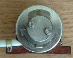
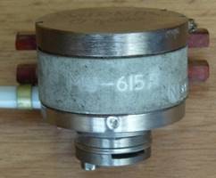
Fig. 5. MU-615 angular displacements feeder
The circuit for measuring analogue
values is one of the fundamental problems arising from the selection of the
right sensor and its adaptation to the on-board recorder installation. Even if
it only includes a resistive sensor and a system for data acquisition,
obtaining accurate measurements requires many complex issues to be taken into
account.
The types of measuring sensors for
flight parameters operating in FDR systems on military aircraft is determined
by the NO-16-A200 standard, as follows:
1.
Disposable commands sensors
2.
Strain torque gauges
3. AC
sensors (differential)
4. DC
sensors (differential)
5.
Synchros
6. Digital
signal sensors
7.
Magnets (synchro with permanent magnets)
8.
Tachometric generators
9. AC
frequency sensors
10.
Thermocouples
11. Resolvers
12.
Accelerometers [6]
3.3. The essence of
parameter measurements
Figure 6 presents a classic work
(measuring) system containing a resistor in a sensor circuit as the measuring element. Although the block diagrams of all
analogue signal strings look similar, the parameters of each block depend on
many factors, of which the most important are the change in resistance of the
sensor per unit change of the measured value (and
thus the change in voltage), the distance from the sensor to the measurement
system (i.e., measurement error due to the resistance of wires), the type of
disturbance and the required accuracy.
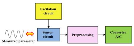
Fig. 6. A general diagram of an
analogue measuring system
The measuring transmitter can process the non-electric signal (N) in relation to the
size of the electrical (E) value, in two ways:
1) Directly, by a single
elementary transducer of non-electrical value for either electrical (N/E) or non-electrical
(N/N) values. Such a transducer serves as a sensor. For example, the sensor
function directly corresponds to the thermocouple with two different metals,
joined at one end. The thermoelectric power is generated between the free ends,
caused by the temperature difference of the measurement weld and the free ends
(N/E processing).
2) Indirectly, as a result of
preprocessing by the elementary converter N/N, which measures the
non-electrical value for other non-electric values.
This is easily measurable for the purposes of further processing by the N/E
transmitter in order to obtain a measurement result. An example of this is a
pressure transducer with a steel membrane (Figure 7).
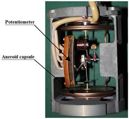
Fig. 7. DAS speed feeder (indirect converter)
The difference in measured pressure is first processed by a resilient mechanical
transducer in relation to other non-electric signal deformations of the
membrane, and then converted to the relative resistance change. The
potentiometer does not respond directly to the measurand value (differential
pressure), but to the deformation of the membrane. In this case, the measuring pressure transducer comprises two elementary converters: N/N and N/E.
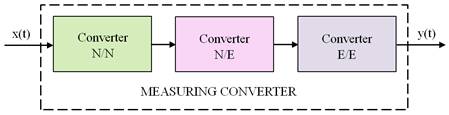
Fig. 8. Block diagram of the measuring converter of non-electrical value
(N: non-electrical value, E: electric value)
Source: [2]
Except for the
N/N and N/E converters, E/E elementary transducers are often used as measuring converters (Figure 8) in order to implement the
basic functions of the measuring transducer or the matching electrical output
signal of the N/E sensor and the parameters of the rest of the measurement path
[3]. The above-mentioned parameters determine:
– The type of excitation
– How to enable the sensor in relation to the measurement
path
– The required value of the gain factor for the
recorder acquisition circuit and the analogue-digital converter (ADC)
– The resolution and range of the input of the ADC
– The type of protection against disturbance (filter)
– The setting of the threshold for cut-off noise
The proper selection of a feeder for
parameter measurements and execution in accordance with technical
guidelines for network connections between the feeder and recorder
increases the accuracy of the measurement path on the feeder line, i.e., the
recorder arrangements block. The fulfilment of this condition greatly limits
the possibility of occurrence of the measurement
error for the parameter machining process. It is very important that the
falsified information entered into the system by the feeder can turn during the
operation of the aircraft in the case of a systematic error whose consequences
can be catastrophic. An example of an incorrect “matching” feeder and the
measuring track is the application of conductors,
which is inconsistent with the requirements of the manufacturer’s resistivity
in a system for measuring the exhaust gas temperature (thermocouple). An
example of the wrong configuration of the measurement path is the use of an
incorrect feeder in the channel in terms of height or speed. The application of
a feeder with the wrong range of a potentiometer reduces the measurement
sensitivity. However, the fundamental issue concerns the properties of the
aneroid, which controls the potentiometer brush. The “sensitivity” box and
range of measured values for the physical parameter are determined by the
dimensions. In the first case, we are dealing with the accuracy of a measuring
point, and in the second with the risk of possible damage (blowing) if the
acceptable range is exceeded. The differences in external dimensions, and in
turn the size of the aneroid cans, are shown in Figure 9.
Regardless of the type of measuring transducer (Figure 8), there is always an analogue signal at its output. Taking into consideration such issues as compression, transmission and storage of data, the analogue signal in subsequent stages is subject to digital processing [5].
The signal from the feeder is passed
to the acquisition block of the recorder, and then undergoes transformation into
digital form. Transforming is performed in the recorder arrangements block
through an ADC. To assess the risk of error at this stage of signal processing,
one should carry out an overall analysis of the operation of the transmitter. The operation of an ADC is shown the figure 11.
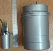
Fig. 9. Comparison of speed feeders: Mdd-Te 0-1.5 and DAS
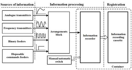
Fig. 10. Block diagram of the
recorder system
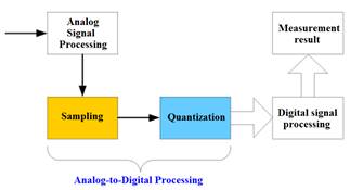
Fig. 11. The process of signal
processing
The process of analogue-digital
conversion consists of three basic operations: sampling, quantization and
coding. Sampling involves collecting (definite and uniform) time samples of an
analogue signal and recording the instantaneous values of the samples taken.
Quantization involves dividing a continuous set of values of the signal into a
finite number of well-defined, adjacent compartments and determining the so-called quantization levels, or
specific values of each compartment representing all values in this range [7];
each sample is assigned to the corresponding (closest) level of quantization,
while, in the encoding process, it is attributed its coded number. Thus, each
sample of the analogue signal corresponds to the code word constituting the
digital, usually binary, record of a certain level of quantization (Figures 12-13):
Fig. 12. The theoretical (ideal)
action of the analogue converter
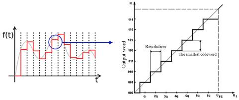
Fig. 13. The practical (real) action
of an ADC
One of the major mistakes in the
processing of the analogue signal into a digital one is the quantization error,
also known as the resolution mistake. It is a systematic error, which amounts
to ±ULSB/2, which is equal to half of the input voltage variation, which causes
a change in the lowest number position. This error can be treated as an
additional interfering signal and is often called quantization noise.
The ideal characteristics of ADCs
can be represented as a stepped line assigning individual compartments of a
processed input voltage-specified digital signal (code word). Actual converters
deviate from the ideal characteristics. In practice, we have to deal with three
types that may occur as a result of the transformation of the AC transducer
signal: zero offset error, amplification error and non-linearity error (Figure
14). The reasons for the error are mostly the ageing of components and
temperature variations.
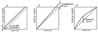
Fig. 14. Illustration
of the definitions: 1) zero error, 2) amplification error,
3) linearity error of the total
4. CONCLUSION
The use of on-board recorders in both state and civil aviation is becoming more common. On the one hand, safety considerations and the possibility of using these devices in other areas of aviation, as support for flight training and prevention in the operation of the aircraft, have meant that they have become, in a sense, universal. The ability to capture virtually any parameter of the aircraft allows for the most accurate way to describe the status and situation of the aircraft during a flight. However, it is not the number of recorded parameters, but the accuracy of their measurement that allows us to get closer to the actual (physical) conditions in the air. Maintaining the required accuracy of parameter measurements consists of many factors, occurring at different stages of operating on-board recorders. Across the entire spectrum of recorded parameters, only single commands offer overall measurement accuracy. For this group of signals, the total measurement accuracy is based on zero-one architecture. It is quite different in the case of the accuracy of measurement parameters, where the accuracy of the measurement should be understood in the overall context, i.e., from the moment of measuring the phenomenon to the reading of the measured physical value. All elements included in the measurement path (measurement, processing and registration) must meet specific performance requirements. The record from the completed SP flight is not only material for analysis in the field of the quality of the task in the air, but also an important component with which to assess the technical condition of the aircraft and thus must be taken into account in terms of accident prevention. The aircraft, as a complex system [4], imposes quantitative requirements on the FRD (the number of recorded parameters), as well as requires the use of measuring tracks that ensure the objective measurement of the phenomenon.
Examples of factors that may cause the registration of
false information have been cited in this article, indicating that errors in
the measurement circuit result from a level of accuracy limited by technological
devices. Maintaining the proper standards, in accordance with the technical
requirements of the FDR system’s operation, imposes certain criteria that
should be met by the personnel operating the FDR, as well as the personnel
performing the reading and parameter analysis.
References
1. ICAO. 2008. Annex 6 (Operation of Aircraft).
2. Gawędzki W. 2010. Electrical Measurements of Non-electrical Quantities. Cracow: AGH.
3. Kester W. 2012. Analog-digital Conversion. Legionowo: BTC.
4. Lewitowicz J. 2006. The Basics of Aircraft Operation. Warsaw: ITWL.
5. Marwen C., G. Ewers. 1999. Outline of Digital Signal Processing. Warsaw: WKŁ.
6.
Defensive
Standard No. NO-16-A200 (Military Aircraft: On-board Catastrophic Recorders –
Requirements and Tests). Official Journal of the MON
4, Pos. 63.
7.
Tumański
S. 2007. Measurement Technology.
Warsaw: WNT.
8.
ATM
Production Company Sp. z o.o. Available at:
http://www.atmavio.pl/lotnictwo/wyroby-dla-lotnictwa-cywilnego/rejestratory-szybkiego.
Received 16.10.2017; accepted in revised form 24.01.2018
![]()
Scientific Journal of
Silesian University of Technology. Series Transport is licensed under
a Creative Commons Attribution 4.0 International License