Article citation information:
Krasuski, K., Ćwiklak, J. Application of the DGPS method for the precise positioning of an aircraft in air transport. Scientific Journal of Silesian University of Technology. Series Transport. 2018, 98, 65-79. ISSN: 0209-3324. DOI: https://doi.org/10.20858/sjsutst.2018.98.7.
Kamil KRASUSKI[1],
Janusz ĆWIKLAK[2]
APPLICATION
OF THE DGPS METHOD FOR THE PRECISE POSITIONING OF AN AIRCRAFT IN AIR TRANSPORT
Summary. This article presents research results concerning the
determination of the position of a Cessna 172 aircraft by means of the DGPS
positioning method. The position of the aircraft was recovered on the basis of
P1/P2 code observations in the GPS navigation system. The coordinates of the
aircraft were designated due to the application of the Kalman forward-filtering
method. The numerical calculations were conducted using RTKLIB software in the
RTKPOST module. In the scientific experiment, the authors used research
materials from the test flight conducted by a Cessna 172 aircraft in the area
of Dęblin in the Lublin Voivodeship in south-eastern Poland. The research
experiment exploited navigation data and GPS observation data recorded by the
geodetic Topcon Hiper Pro receiver mounted in the cockpit of the Cessna 172 and
installed on the REF1 reference station. The typical accuracy for recovering
the position of the Cessna 172 with the DGPS method exceeds in the region of 2
m. In addition, the authors specify the parameters of availability, integrity
and continuity of GNSS satellite positioning in air navigation. The obtained
findings of the scientific experiment were compared with the International
Civil Aviation Organization’s (ICAO’s) technical standards.
Keywords: air
navigation, air transport, DGPS method, accuracy, ICAO, Kalman filter,
integrity
1. INTRODUCTION
The DGPS positioning technique
refers to a differential measurement approach, which can be executed both in
near real time and in postprocessing. The DGPS measurement method requires a
rover receiver and a base reference station from the user. In near real time,
the coordinates of the rover receiver’s antenna are determined on the basis of
differential corrections sent via the NTRIP protocol in the RTCM format from
the service of the reference station’s network [12]. In the case of
calculations during postprocessing, the coordinates of a rover receiver are
determined on the basis of registered raw GNSS satellite observations by the
rover receiver and the base reference station. In the DGPS measurement
technique, mostly single-frequency (or dual-frequency) code observations are
used from one or more GNSS navigation systems [3].
In
practice, the DGPS positioning technique allows for reducing or eliminating a
number of systematic errors in GNSS satellite measurements. Systematic errors
that are related to the satellite clock and the receiver are completely
eliminated in the DGPS method. In this way, it is possible to remove the
satellite clock error correction, the receiver clock error correction, the
relativistic satellite clock correction, TGD hardware delay for the satellite
and the RDCB instrumental bias for the receiver. On the other hand, the impact
of the ionosphere correction and the troposphere correction is reduced at the
differentiation stage for the observation equations of the mathematical model
[2]. It is worth mentioning that, in the DGPS measurements, it is crucial to
determine the characteristics of the antenna of the rover receiver and the base
reference station.
The DGPS measurement
method is used for positioning in static and kinematic modes. In the kinematic
mode, the method of DGPS positioning provides, for example, the designation of
the precise position of the aircraft in air navigation [6]. The recovery of a
reliable aircraft position affects the improvement in the safety of air
operations in airspace. In addition, the technique of DGPS positioning is
important in the development of aircraft approach procedures for landing with
the use of the GNSS system in air transport [7].
The aim of this investigation is to
recover the possibility of aircraft coordinates using the DGPS positioning
method in air navigation. In the test research, we recovered the position of a
Cessna 172 aircraft by executing a test flight around the airfield in Dęblin.
The position of the aircraft was recovered using RTKLIB software in the RTPOST
module. Satellite data were used for the numeric calculations, which were
obtained from a Topcon Hiper Pro received mounted on board the Cessna 172 and
installed as a physical reference station at the military airfield in Dęblin.
The calculations were made in the postprocessing mode for the GPS code
observations.
2. RESEARCH METHODOLOGY
The basic observation equations in the DGPS
positioning method rely on the use of the operation of double difference of GPS
code observations, as follows [4,8]:
 (1)
(1)
where:
![]() is the operator of the double difference for code
measurements, which allows for comparing the difference in code measurements
for two satellites tracked by two receivers
is the operator of the double difference for code
measurements, which allows for comparing the difference in code measurements
for two satellites tracked by two receivers
![]() is the operator of a single difference for code measurements,
which allows for determining the difference in code measurements for two
satellites tracked by one receiver
is the operator of a single difference for code measurements,
which allows for determining the difference in code measurements for two
satellites tracked by one receiver
![]() is the vector in the space between the base
station (
is the vector in the space between the base
station (![]() ) and the rover receiver (
) and the rover receiver (![]() ) mounted on board the aircraft
) mounted on board the aircraft
![]() is the value of the double code difference (expressed in
metres) on the vector
is the value of the double code difference (expressed in
metres) on the vector ![]() between the satellites
between the satellites
![]() and
and ![]() on the L1 frequency in
the GPS system
on the L1 frequency in
the GPS system
![]() is the value of the double code difference (expressed in
metres) on the vector
is the value of the double code difference (expressed in
metres) on the vector ![]() between the satellites
between the satellites
![]() and
and ![]() on the L2 frequency in
the GPS system
on the L2 frequency in
the GPS system
![]() is the geometric distance of the vector
is the geometric distance of the vector ![]() for the double code
difference (expressed in geocentric coordinates XYZ)
for the double code
difference (expressed in geocentric coordinates XYZ)
![]() is the value of the ionosphere delay on the L1 frequency for
the double code difference
is the value of the ionosphere delay on the L1 frequency for
the double code difference
![]() is value of the ionosphere delay on the L2 frequency for the
double code difference
is value of the ionosphere delay on the L2 frequency for the
double code difference
![]() is the relationship of the ionosphere delay on the L1 and L2
frequency
is the relationship of the ionosphere delay on the L1 and L2
frequency
![]() is the scaling coefficient
is the scaling coefficient
![]() is the L1 frequency in the GPS system
is the L1 frequency in the GPS system
![]() is the L2 frequency in the GPS system
is the L2 frequency in the GPS system
![]() is the value of the troposphere delay for the double code
difference
is the value of the troposphere delay for the double code
difference
![]() is the multipath effect and noise measurement at the L1
frequency for the code measurements
is the multipath effect and noise measurement at the L1
frequency for the code measurements
![]() is the multipath effect and noise measurement at L2 frequency
for the code measurements
is the multipath effect and noise measurement at L2 frequency
for the code measurements
The observation equations (1) were recorded for the code observations
P1/P2 for the carrier frequencies L1/L2 in the GPS navigation system. In
Equation (1), the unknown parameters are the coordinates of the aircraft
involved in the geometrical distance factor. The parameters of the ionosphere
and troposphere delays are expressed by deterministic models. The values of the
multipath effect are expressed on the basis of empirical models. The
observation model from Equation (1) is usually solved in two stages, using
Kalman filtering; see below [1]:
a) Process of “prediction”:
 (2)
(2)
where:
![]() is the matrix of coefficients
is the matrix of coefficients
![]() is the estimation of the values of the designated parameters
a priori from the previous step
is the estimation of the values of the designated parameters
a priori from the previous step
![]() is the estimation of the values of covariance a priori from
the previous step
is the estimation of the values of covariance a priori from
the previous step
![]() is the prediction of the state value
is the prediction of the state value
![]() refers to the predicted covariance values
refers to the predicted covariance values
![]() is the variance matrix of the noise of the measurement
process
is the variance matrix of the noise of the measurement
process
b) Process of
“correction”:
 (3)
(3)
where:
![]() is the covariance matrix of measurements
is the covariance matrix of measurements
![]() is the matrix of partial derivatives
is the matrix of partial derivatives
![]() is the Kalman gain matrix
is the Kalman gain matrix
![]() is the vector of measured values
is the vector of measured values
![]() is the unit matrix
is the unit matrix
![]() refers to the parameters determined a posteriori
refers to the parameters determined a posteriori
![]() is the covariance matrix of parameters determined a
posteriori
is the covariance matrix of parameters determined a
posteriori
The Kalman filtering process is
performed sequentially for all measured epochs registered by the GNSS receiver
mounted on board the aircraft. Additionally, in the stochastic process of
developing the GPS observations, the accuracy of positioning the aircraft is
also determined. It should be emphasized that the designated coordinates of the
aircraft and their accuracies are expressed in the geocentric coordinates XYZ.
3. RESEARCH EXPERIMENT
The
verification of applying the DGPS technique in air navigation was carried out
in an air experiment using a Cessna 172 aircraft. The air experiment was
conducted on a military airfield in Dęblin and in the surrounding area. The
test flight on the Cessna 172 was made in the morning, from 09:39:03 to
10:35:03, according to the time of the GPS navigation.
Figure 1
shows the trajectory of the Cessna 172 on the horizontal plane. The coordinates
of the aircraft were expressed using BLh ellipsoidal coordinates (B: latitude,
L: longitude, h: ellipsoidal height). In order to transform the coordinates of
the aircraft from the XYZ geocentric coordinate frame into the BLh ellipsoidal
frame, the Helmert transformation was used [15, 18]. Figure 1 shows the
location of the reference station REF1, which was used to recover the precise
trajectory of the flight of the Cessna
– Latitude: 51° 33’ 19.92606” N
– Longitude: 21° 52’ 08.72275” E
– Ellipsoidal height:
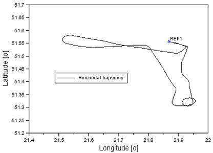
Fig. 1. The horizontal trajectory of
the flight of the Cessna 172
During the
flight test, the geodetic receiver Hiper Pro was installed on board the Cessna
172 (see Figure 2). The aim of the Topcon Hiper Pro rover receiver was to
collect raw GNSS observations in order to recover the coordinates of the
aircraft in postprocessing. The frequency of data registration in the rover
receiver was also equal to 1 s. Furthermore, the SAMSET system, which monitored
the position of the aircraft in near real time, was installed on board the
Cessna 172.
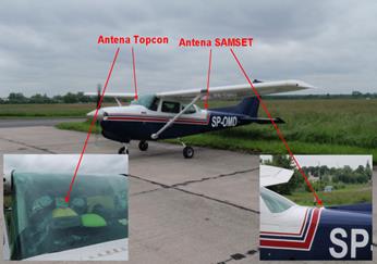
Fig. 2. The GNSS receiver in the
pilot’s cabin of the Cessna 172
The simultaneous
synchronization of GNSS observations from the Topcon Hiper Pro rover receiver
and the receiver of the REF1reference station allowed for the designation of
the Cessna 172’s position, as well as the determination of the positioning
accuracy. The coordinates of the aircraft were designated on the basis of
a single baseline (spatial vector ![]() ), i.e., baseline (vector) REF1-Cessna
), i.e., baseline (vector) REF1-Cessna
-
GNSS system: GPS
system
-
GNSS observations:
code observations P1/P2 in the GPS system
- Construction of the observation equations: double
difference for code observations in the GPS system
-
Data source of the
ephemeris GPS satellites: GPS navigation data message
-
Source of the GPS
observation: RINEX 2.11 file
-
Method for
determining the coordinates of the GPS satellites: based on the parameters of
the Kepler orbit
-
Correction of the pseudorange from the satellite to
the receiver antenna: applied
-
Effect of the earth’s rotation: applied
-
Sagnac effect: applied
-
Correction of the satellite clock: eliminated
-
Relativistic effects: eliminated
-
TGD hardware delay: eliminated
-
Receiver hardware delay: eliminated
-
Troposphere model:
Saastamoinen
-
Ionosphere
correction model: Klobuchar
-
Source of
ionosphere correction: GPS navigation data message
-
Receiver antenna
phase centre: based on the ANTEX IGS08 file
-
Elevation angle:
10°
-
Observation
weighting: applied
-
A priori standard
deviation of code observations:
-
Initial values of
aircraft coordinates: based on the RINEX file header
-
Frame of
coordinates: geocentric XYZ and ellipsoidal BLh (ultimately ETRF ‘89)
-
Method of
calculations: Kalman forward-filtering
-
Positioning method: DGPS/DGNSS
-
Positioning mode: kinematic
-
Computational mode: postprocessing
-
Interval of calculations: 1 s
-
Blunder error detection in GPS measurements: RAIM
module algorithm
-
Number of iterations in the measurement epoch: five
-
Maximum value of the DOP coefficient: 30
-
Final recording of coordinates: coordinates in the XYZ
geocentric frame and the BLh ellipsoidal frame
-
Correction of the receiver clock: eliminated
-
Geodynamic and tidal effects: applied
-
Rover receiver: Topcon Hiper Pro mounted in a Cessna
172 aircraft
-
Base receiver:
Topcon Hiper Pro fixed at the REF1 reference station
4. RESEARCH RESULTS
The
examination of the use of GNSS satellite technology in air navigation is
focused on determining four basic positioning parameters: availability,
accuracy, continuity and integrity. The availability parameter is determined
based on the visibility of the GNSS constellation during the measurement
session. In addition, when tracking the GNSS satellite constellation, no break
must appear in the satellite positioning due to the lack of navigation data and
observation data. Therefore, monitoring the available satellites of a given
constellation of the GNSS system (e.g., the GPS system) is of crucial
importance. In accordance with Annex 10 to the Convention on International
Civil Aviation, entitled “Radio Communication”, Volume I “Radio Navigation
Aids”, a typical parameter value of the availability of the GPS system is 0.99
(99%) [9]. This means, de facto, that, during the executed air test, the
continuity of tracking a GPS constellation equals at least 0.99 of the duration
of the whole flight. Thus, the lack of data or GPS system failure may occur
only in the case of 1% of the duration of the flight test. Figure 3 shows the
number of available GPS satellites during the executed test flight in Dęblin on
1 June 2010.
Fig. 3. Number of satellites in the GPS constellation
Based on
Figure 3, it can be concluded that the number of available GPS satellites
during the test flight ranged from five to nine. Therefore, when executing the
test flight, the tracking of the GPS constellation was still available.
Likewise, navigation data were not missing. Therefore, the availability
parameter of the constellation of GPS satellites was above 0.99 (99%), which
complies with the ICAO requirements. It should be added that the number of
available GPS satellites in Figure 3 de facto expresses the total number of GPS
satellites tracked jointly by the rover receiver mounted on board the Cessna
172 and the REF1 reference station.
An
important parameter in determining the quality of satellite positioning is the
accuracy of the set position. The accuracy parameter in the GNSS measurements
is represented by the values of the standard deviation for the designated
coordinates of the aircraft. In this case, the accuracy of the set position of
the Cessna 172 aircraft can be referred to geocentric XYZ coordinates, as
below:
![]() (4)
(4)
where:
![]() is the accuracy of the aircraft position along the
X-axis
is the accuracy of the aircraft position along the
X-axis
![]() is the accuracy of the aircraft position along the
Y-axis
is the accuracy of the aircraft position along the
Y-axis
![]() is the accuracy of the aircraft position along the
Z-axis
is the accuracy of the aircraft position along the
Z-axis
or
adequately expressed in the coordinates of the ellipsoidal BLh, as follows
[13]:
![]() (5)
(5)
where:
![]() is the covariance matrix in the geodetic frame (BLh),
is the covariance matrix in the geodetic frame (BLh), ![]()
![]() is the transition matrix from the geocentric (XYZ) to the
geodetic frame (BLh)
is the transition matrix from the geocentric (XYZ) to the
geodetic frame (BLh)
![]() is
the standard deviation in latitude
is
the standard deviation in latitude
![]() is
the standard deviation in longitude
is
the standard deviation in longitude
![]() is
the standard deviation in ellipsoidal height
is
the standard deviation in ellipsoidal height
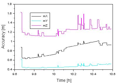
Fig. 4. The accuracy of the Cessna 172
aircraft in the XYZ geocentric frame
Figure 4
shows the values of positioning accuracy of the Cessna 172 in the XYZ
geocentric frame; see Equation (4). The average positioning accuracy along the
X-axis is
Figure 5
shows the values of positioning accuracy in the BLh ellipsoidal frame; see
Equation (5). The average positioning accuracy of geodetic latitude B is equal
to
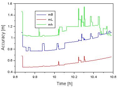
Fig. 5. The accuracy of the Cessna 172
aircraft in the BLh geodetic frame
Annex 10
to the Convention on International Civil Aviation, entitled “Air
Communication”, Volume I “Radio Navigation Aids”, specifies the technical
standards for the parameter of accuracy of satellite positioning using the GPS
navigation system in civil aviation [9]. The ICAO imposed the framework for
commissioning the GPS system on civilian users in aviation. The ICAO’s accuracy
standards are matched with air operations for a specific flight plane of an
aircraft in civil aviation. For navigation on the horizontal plane, the
accuracy of flight navigation LNAV ranges from
Figure 6
shows the positioning accuracy of the Cessna
![]() (6)
(6)
The
average value of the MRSE parameter is
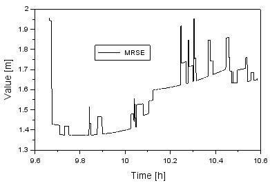
Fig. 6. The values of the MRSE parameter
 \
\
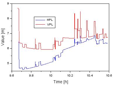
Fig. 7. The values of the HPL/VPL parameters
The parameter of integrity for the
DGPS satellite positioning in civil aviation is of the utmost importance during
the execution of air operations in airspace. In civil aviation, the integrity
parameter is specified by means of safety levels. In practice, the levels of
safety are referenced to navigation on both the horizontal and the vertical
planes. On the horizontal plane, the safety level is determined by the HPL
parameter, and by means of the VPL parameter on the vertical plane. The
approximate values of the HPL and VPL safety parameters are determined on the
basis of Equation (7) [10]:
 (7)
(7)
where:
![]() for
the horizontal plane
for
the horizontal plane
![]() for
the vertical plane [5]
for
the vertical plane [5]
Figure 7
shows the obtained values for the HPL and VPL parameters. The average value of
the HPL parameter is
Annex 10
to the Convention on International Civil Aviation, entitled “Air
Communication”, Volume I “Radio Navigation Aids”, specifies the technical
standards for the parameter of integrity for satellite positioning using the
GNSS navigation system in civil aviation [9]. The integrity values for GNSS
satellite positioning in civil aviation were specified for the selected type of
aircraft approach for landing. Within the framework of the ICAO’s technical
standards, there are three types of aircraft approach to landing with the GNSS
sensor:
– Non-precision approach (NPA)
– Approach procedures with vertical
guidance (APV)
- Precision approach (PA)
In Poland,
the largest civilian passenger and transport airports have implemented
technical regulations for the NPA with the GNSS sensor. The framework for the
operation and application of the GNSS sensor for this approach was introduced
by the Polish Air Navigation Services Agency. It must be underlined that, with
regard to the NPA, the accuracy of determining the position of the aircraft on
the horizontal plane is equal to
The
obtained values of the HPL and VPL parameters can be used directly or
indirectly to determine the continuity of GNSS satellite positioning in civil
aviation. The parameter of continuity specifies and defines the gaps in
tracking down a moving object with the use of GNSS satellite techniques.
Furthermore, the parameter of continuity indicates possible failure and a lack
of data from the GNSS positioning system. The mathematical formula to determine
the parameter of continuity is as follows [11]:
![]() (8)
(8)
where:
![]() is the
maximum alert value on the horizontal plane
is the
maximum alert value on the horizontal plane
![]() is the maximum alert value on the vertical plane
is the maximum alert value on the vertical plane
The
parameter values of HAL and VAL specify the maximum alert levels for the
integrity of GNSS positioning during the selected type of aircraft approach for
landing. The continuity parameter is exceeded when the HPL is larger than HAL,
or when VPL is larger than VAL. Within the framework of the NPA using GNSS, the
HAL value is
5. DISCUSSION
In this section, the obtained
trajectory of an aircraft from a DGPS application was verified and compared
with results from the DGLONASS solution. The aircraft position was estimated
using the DGLONASS method in the RTKPOST library within the RTKLIB software
package. The Kalman filter solution was applied as a stochastic scheme of
designation for the aircraft coordinates in the RTKLIB program. The coordinates
of the aircraft were recovered with an interval of 1 s using the DGLONASS
method. The aircraft coordinates from the DGLONASS solution are referenced to
the ETRF’89 frame, similar to the DGPS method.
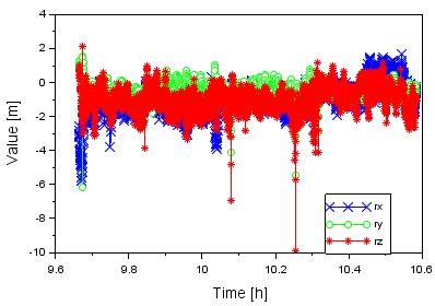
Fig. 8. The difference
in the XYZ geocentric coordinates of the aircraft between the DGPS and DGLONASS
solutions
The difference in the aircraft
coordinates in the geocentric XYZ frame between the DGPS and DGLONASS solutions
was calculated as follows:
 (9)
(9)
where:
![]() is the x coordinate of the aircraft based on the DGPS
solution – see Equation (1)
is the x coordinate of the aircraft based on the DGPS
solution – see Equation (1)
![]() is the x coordinate of the aircraft based on the DGLONASS
solution
is the x coordinate of the aircraft based on the DGLONASS
solution
![]() is the y coordinate of the aircraft based on the DGPS
solution – see Equation (1)
is the y coordinate of the aircraft based on the DGPS
solution – see Equation (1)
![]() is the y coordinate of the aircraft based on the DGLONASS
solution
is the y coordinate of the aircraft based on the DGLONASS
solution
![]() is the z coordinate of the aircraft based on the DGPS
solution – see Equation (1)
is the z coordinate of the aircraft based on the DGPS
solution – see Equation (1)
![]() is the z coordinate of the aircraft based on the DGLONASS
solution
is the z coordinate of the aircraft based on the DGLONASS
solution
Figure 8
presents the values of the ![]() coordinates based on a comparison of the DGPS and DGLONASS
solutions. The mean difference for the x coordinate of the aircraft equals
coordinates based on a comparison of the DGPS and DGLONASS
solutions. The mean difference for the x coordinate of the aircraft equals ![]() is between
is between ![]() parameter is between
parameter is between ![]() term is between
term is between
6. CONCLUSIONS
This article analysed the
applicability of the DGPS positioning method in determining aircraft
coordinates in air navigation. To this end, we recovered the position of a
Cessna 172 aircraft in postprocessing. The calculations were carried out using
RTKLIB software in the RTKPOST module by exploiting GPS code observations. The
mathematical model for designating the aircraft position was based on the use
of observation equations for dual code differences. In the research experiment,
we used the P1/P2 code observations recorded by the geodetic receivers mounted
on board the Cessna 172 and the Topcon Hiper Pro receiver installed at the
reference station REF1. The materials for research came from a test flight,
which was conducted at the military airfield in Dęblin. Within the framework of
the conducted research, we recovered the trajectory of the Cessna 172 using the
Kalman forward-filtering forward base solution. The article also analysed the
GNSS satellite positioning for determining the parameters of availability,
accuracy, integrity and continuity in civil aviation. The parameter of
availability of the GPS satellite constellation was 100%, which facilitated a
continuous navigation solution for the position of the Cessna 172 aircraft. The
accuracy of the designated coordinates of the Cessna 172 was higher than
Acknowledgements
The authors would like to thank
Tomoji Takasu for making available the RTKLIB software package on the website
www.rtklib.com.
References
1.
Ali A.S.A. 2013. Low-cost Sensors-based Attitude Estimation for Pedestrian Navigation in
GPS-denied Environments. PhD thesis. UCGE Reports Number 20387: 43-46.
University of Calgary, Alberta, Canada.
2.
Ali Q., S.
Montenegro. 2014. “A Matlab implementation of differential GPS for low-cost GPS
receivers”. TransNav 8(3): 343-350.
DOI: 10.12716/1001.08.03.03.
3.
Bakuła Mieczysław.
2010. “Network code DGPS positioning and reliable estimation of position
accuracy”. Survey Review 42(315):
82-91. DOI: 10.1179/003962610X12572516251448.
4.
Bosy Jarosław.
2005. “Precise processing of satellite GPS observations in local networks
located in mountain areas”. Zeszyty
Naukowe Akademii Rolniczej we Wroclawiu 522: 13-16.
5.
Grunwald
Grzegorz, Adam Ciećko, Mieczysław Bakuła, Rafał Kaźmierczak. 2016. “Examination of GPS/EGNOS integrity in north-eastern
Poland”. IET Radar, Sonar & Navigation 10(1): 114-121. DOI:
10.1049/iet-rsn.2015.0053.
6.
Grzegorzewski
Marek, Waldemar Jaruszewski, Andrzej Fellner, Stanisław Oszczak, Aleksander
Wasilewski, Zofia Rzepecka, Jacek Kapcia, Tadeusz Popławski. 1999. “Preliminary results of DGPS/DGLONASS aircraft
positioning in flight approaches and landings”. Annual of Navigation 1: 41-53.
7.
Grzegorzewski
Marek. 2005. “Navigating an aircraft by means of a position potential in
three-dimensional space”. Annual of
Navigation 9: 1-111.
8.
Hofmann-Wellenhof Bernhard, Herbert Lichtenegger, Elmar Wasle. 2008. GNSS – Global Navigation Satellite Systems:
GPS, GLONASS, Galileo, and More. Vienna and New York: SpringerWienNewYork.
ISBN 978-3-211-73012-6.
9.
International
Civil Aviation Organization. 2006. ICAO
Standards and Recommended Practices (SARPS), Annex 10, Volume I (Radio
Navigation Aids). Available at:
http://www.ulc.gov.pl/pl/prawo/prawo-mi%C4%99dzynarodowe/206-konwencje.
10.
Jokinen Altti,
Shaojun Feng, Carl Milner, Wolfgang Schuster, Washington Ochieng, Chris Hide,
Terry Moore, Chris Hill. 2011. “Precise point
positioning and integrity monitoring with GPS and GLONASS”. Paper presented at the European Navigation
Conference 2011, London, UK.
11.
Kaplan Elliott,
Hegarty, Christopher. 2017. Understanding
GPS/GNSS Principles and Applications. Norwood, MA: Artech House. ISBN-13:
978-1-63081-058-0.
12.
Kaźmierczak
Rafał., Grunwald Grunwald., Bakuła Mieczysław. 2011. “The use of RTCM 2.X DEKODER software for analyses of KODGIS and
NAWGIS services of the ASG-EUPOS system”. Technical
Sciences 14(2): 229-243.
13.
Osada
Edward. 2001. Geodesy, Wrocław:
Oficyna Wydawnicza Politechniki Wrocławskiej. ISBN 83-7085-663-2.
14.
Przestrzelski
Paweł, Bakuła Mieczysław, Galas Roman. 2017. “The integrated use of GPS/GLONASS observations in network code
differential positioning”. GPS Solutions 21(2):
627-638. DOI: https://doi.org/10.1007/s10291-016-0552-y.
15.
Sanz Subirana
Jaume, Jose Miguel Juan Zornoza, Manuel Hernández-Pajares. 2013. GNSS Data Processing, Volume
I: Fundamentals and Algorithms. Noordwijk, Netherlands: ESA Communications, ESTEC. ISBN 978-92-9221-886-7.
16.
Seeber Gűnter.
2003. Satellite Geodesy. 10785
Berlin, Germany: Walter de Gruyter GmbH & Co. KG. ISBN 3-11-017549-5.
17.
Takasu Tomoji. 2013. RTKLIB Ver. 2.4.2 Manual, RTKLIB: An Open Source
Program Package for GNSS Positioning. Available at: http://www.rtklib.com/prog/manual_2.4.2.pdf.
Received 07.12.2017; accepted in revised form 25.02.2018
![]()
Scientific Journal of
Silesian University of Technology. Series Transport is licensed under
a Creative Commons Attribution 4.0 International License