Article citation information:
Faltinová, E., Mantič, M., Kuľka, J., Kopas, M. Reliability analysis of crane lifting mechanism. Scientific Journal of Silesian University of Technology. Series Transport. 2018, 98, 15-26. ISSN: 0209-3324. DOI: https://doi.org/10.20858/sjsutst.2018.98.2.
Eva FALTINOVÁ[1],
Martin MANTIČ[2],
Jozef KUĽKA[3],
Melichar KOPAS[4]
RELIABILITY
ANALYSIS OF CRANE LIFTING MECHANISM
Summary. This paper focuses on a reliability analysis of various structural variants of a crane lifting mechanism. The reliability of such a mechanism is a basic requisite for the safe operation of the crane as a whole. The article analyses and jointly evaluates structural solutions for the lifting mechanism in a bridge crane, in order to emphasize the technical aspects of system reliability in this context.
Keywords: lifting mechanism, crane, reliability, technical system, reliability indicators, block diagram
1. INTRODUCTION
In the area
of transport and handling machines or machinery, there are many devices with a
high potential of danger or technical risk. The lifting mechanism of cranes,
which are used, for example, in the transport of hazardous substances, is
representative in this regard. It is possible to improve the reliability of
such devices by taking various measures, e.g., by slowing the process of
deterioration, eliminating the source of deterioration, following the
procedures for operation and maintenance, and using alternate components.
A growing number of components in
complex technical systems, however, has increased the probability of failure.
Given that it is usually possible to improve the indicators of system
reliability by carrying out several appropriate measures, finding a structural
solution is very important too.
To perform a quantitative analysis
of technical system reliability by using reliability indicators, mathematical
methods of probability and statistical probability are applied. The most
relevant methods used for the evaluation of structural reliability, including
the theoretical basis of these methods, are described in [1,2,3]. A specific
approach to reliability is presented in [4], whose authors derive the value of
reliability from the scheduling of an activity with a random duration, such as
travel under congested conditions, concerning questions related to transport.
The ability to forecast machinery failure is vital in order to reduce
maintenance costs, operation downtime and safety hazards. A novel approach to
incorporating information on population characteristics and suspended condition
trending data on historical units into prognoses is presented in [5,6]. A
comprehensive, up-to-date description of all the important methods for the
design, development, manufacture and maintenance of reliable engineering
products and systems can be found in [7,8,9]. Another important aspect of
machine reliability is the reliable maintenance or influence of maintenance on
the reliability of machines and machinery [26,27,28,29,30,31,32].
Reliability-centred maintenance is a method for maintenance planning developed
within the aircraft industry and later adapted to several other industries and
military branches. This method is demonstrated in [10,11].
The reliability aspects of dynamic
systems relating to engineering production plants are described in [12], while
a reliability analysis of technical systems, which considers working
environment parameters, is presented in [13].
A special approach to the questions
of reliability is required in the case of driving systems equipped with piston
combustion engines. Typical examples illustrating this investigation area can
be found in [14,15].
The most important mechanism in
every crane is the lifting mechanism. The motion of a crane lifting mechanism
is considered in [16,17]. A special example of the crane lifting mechanism,
which is installed in a quay container crane, is modelled in [18]. Questions
concerning the bridge crane load spectrum and load distribution are analysed in
[19,20]. An intelligent anti-swing control for the bridge crane is introduced in
[21,22].
This article analyses and evaluates
the technical system reliability relevant to the standard variants of a crane
lifting mechanism, which is typically installed in bridge cranes.
2. METHODS USED FOR CALCULATING RELIABILITY
INDICATORS IN TECHNICAL SYSTEMS
A system refers to a device, which
consists of multiple parts, known as system components. It is important to
understand its structure and the nature of its work to such an extent that we
are able to determine whether or not the failure of a particular component will
cause the entire system to fail. The system of our inquiry, which consists of n components, can be divided into
series, parallel and combined configurations.
The reliability of a technical
system that consists of components can be conveyed numerically by using the
following indicators of system reliability, [23,24]:
F(t) – failure
probability (unreliability
R(t) – failure-free
probability (reliability)
f(t) – failure
probability density
λ(t) – failure
intensity
In order to calculate the
reliability indicators of a technical system, it is necessary:
Ø To know the probability of a failure-free operation
for ri(t), for i = 1, 2, ..., n components.
Ø To draw a reliability block diagram.
A reliability block diagram illustrates how the components are
interconnected in terms of reliability analysis and calculation.
Ø To assume that the individual parts are independent.
This means that the failure, or rather the survival, of a particular system
component does not affect the failure, or rather the survival, of other system
components. Based on this simplification, we can determine the reliability of
fundamental component interconnections.
2.1. Series systems
Series interconnection is a configuration of components in
a reliability block diagram, in which a system failure occurs when at least one
component fails. A reliability block diagram for a series system is shown in
Figure 1.
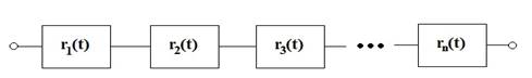
Fig. 1. Reliability
block diagram of series interconnection
Reliability indicators for
series systems are calculated by using the following formulas:
Probability of a failure-free operation in
series systems
![]() (1)
(1)
Probability of failure in series systems
![]() (2)
(2)
Failure probability density in series systems
![]()
Each element is expanded by quantity
![]() , for i = 1, 2, ..., n. Then:
, for i = 1, 2, ..., n. Then:
 (3)
(3)
Failure intensity in series system
 (4)
(4)
The resulting reliability of the
series system is always less value than the reliability of the most unreliable
component from the given system (Figure 2).
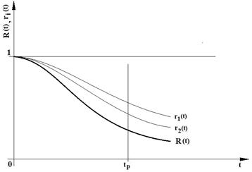
Fig. 2. Time behaviour
of the reliability of the system and components in the case of series
interconnection
2.2. Parallel systems
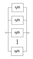
Parallel interconnection is a configuration of components in
the reliability block diagram, in which a system failure occurs when all
components fail. A reliability block diagram for parallel systems is shown in
Figure 3. Reliability indicators for parallel systems are calculated by using the
following formulas:
Probability of failure in parallel systems
![]() (5)
(5)
Probability of a failure-free operation in
parallel systems
![]() (6)
(6)
Failure probability density in parallel systems
Each element is expanded by quantity ![]() , for i = 1, 2, ..., n. Then:
, for i = 1, 2, ..., n. Then:
 (7)
(7)
Failure intensity in parallel systems
![]() (8)
(8)
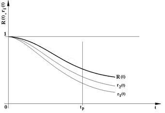
The resulting reliability of the
parallel system is always higher than the reliability of the most reliable
component from the given system (Figure 4).
|
|
|
|
Fig. 3. Reliability block
diagram of parallel interconnection |
Fig. 4. Time
behaviour of the reliability of the system and components in the case of
parallel interconnection |
2.3. Combined systems
Combined systems merge series and parallel subsystems
into a single system. A combined interconnection diagram is shown in
Figure 5.
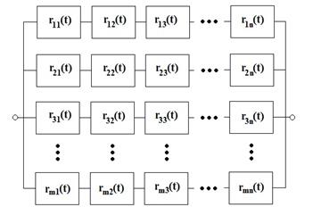
Fig. 5. Reliability block diagram of a combined
interconnection
Reliability indicators for
combined systems are calculated by using the following formulas:
Probability of a failure-free operation in
combined systems
 (9)
(9)
where: i
= 1, 2, ..., m (number of branches in the system); and j = 1, 2, ..., n (number of components in the branches of the
system).
Probability of failure in combined systems
![]() (10)
(10)
Failure probability density in combined systems
![]() (11)
(11)
Failure intensity in combined systems
![]() (12)
(12)
3. RESULTS OF RELIABILITY EVALUATION FOR THE
MAIN STRUCTURAL VARIANTS OF A LIFTING MECHANISM
This chapter presents
a reliability analysis of five solution variants for lifting mechanisms in
bridge cranes.
|
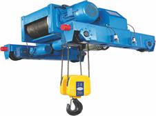
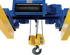
Fig. 6.
Examples of crane lifting mechanism (Demag Cranes) |
Fig. 7. Scheme of crane lifting mechanism |
The first variant (ZM A) represents
the most complex configuration of the lifting mechanisms, whose modification
through structural simplifications creates the other four variants (ZM B to ZM
E).
Figure 6 illustrates typical structural solutions for
lifting mechanisms in bridge cranes. Figure 7 shows a scheme for
a lifting mechanism in its most complex structural configuration (ZM A).
Table 1 presents an overview of structural solutions
for all five variants of lifting mechanisms, i.e., from ZM A to ZM E.
The next section presents the
results of an investigation into the extent to which the probability of
a load drop event can be affected by structural simplifications. For this
purpose, it is necessary to configure reliability block diagrams for each
variant of the lifting mechanism. (Figure 8).
Table 1. Overview of
design differences among the individual variants from
ZM A to ZM E
|
Variant ZM |
Description |
|
ZM A |
Lifting mechanism matches the illustration in
Figure 7 |
|
ZM B |
Like ZM A, but without a support drum
fitting, and with a single rope |
|
ZM C |
Like ZM B, but without an auxiliary brake |
|
ZM D |
Like ZM B, but without a safety brake |
|
ZM E |
Like ZM C, but without a safety brake |
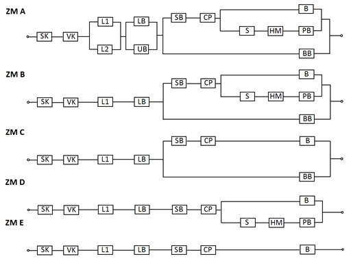
Fig. 8. Reliability
block diagrams of lifting mechanism variants
The designated symbols in the
reliability block diagrams for the individual components of the lifting
mechanism refer to the following:
|
SK –
sheave block with a lifting hook L – rope VK –
balancing block LB – rope
drum including support fitting UB –
support drum fitting SB – drum
clutch |
CP – front
gearbox S – clutch HM – motor
shaft including support fitting BB –
safety brake PB –
auxiliary brake B –
operational brake |
A load drop event, i.e.,
lifting mechanism failure, does not occur if:
o
The
sheave block (SK) or the balancing block does not incur damage (VK)
o
One
of the two ropes is intact
o
The
rope drum, including its support fitting or the support fitting (UB), is intact
o
The
rope drum remains locked
The rope drum remains locked if the
safety brake (BB) is functional, or if the drum clutch (SB) and the gearbox
(CP) transmit the braking torque from the drive. Weibull distribution, in its
following analytical form, was used to describe the failure of the components
in the analysed lifting mechanisms:
![]() (13)
(13)
It is characterized by parameters a (scale parameter), b (shape parameter) and ![]() .
.
The specified distribution is
a suitable failure-free time or life model for machines or equipment that
are affected by fatigue damage. To calculate the probability of failure ![]() according to Weibull distribution,
it is necessary to know the values of its parameters. The parameters were
identified during life tests for the lifting mechanism shafts and their values
were derived from [25]:
according to Weibull distribution,
it is necessary to know the values of its parameters. The parameters were
identified during life tests for the lifting mechanism shafts and their values
were derived from [25]:
![]() = 1,905,802 (number of loading
cycles)
= 1,905,802 (number of loading
cycles)
a =
4,567,187 (number of loading cycles)
b = 0.725
The F(t) function, which conveys the probability of failure, or
alternatively, the probability of a load drop event for each of the five
variants of lifting mechanisms (ZM A to ZM E), is shown in its dynamic
graphical representation in Figure 9.
The calculation and drawing of the
dynamic outcomes were acquired by using ASMBOOL, the software product
specifically designed for this purpose.
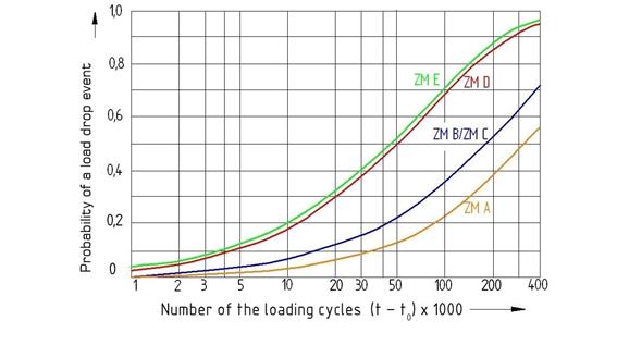
Fig. 9. Probability of
a load drop event for the individual variants of lifting mechanisms, i.e., ZM A
to ZM E
4. DISCUSSION
This article presents the findings of our
investigation into the reliability of technical systems (more specifically,
lifting mechanisms in bridge cranes) by calculating the probability of system
failure, i.e., the probability of a load drop event for five variant designs of
the analysed mechanisms.
Figure 9 illustrates three groups of dynamic
curves for the probability of a load drop event, namely, ZM E/D, ZM C/B and ZM
A, which differ in the gradient of the increasing values of probability.
The ZM A variant appears to best suit the
criteria of reliability and safety, since the probability of a load drop event
in this case developed at the slowest rate, and reached the lowest values for
all other outcomes. In the real world, this would be caused by the fact that
the ZM A mechanism features the most alternate safety components, i.e., brakes.
The dynamic outcomes for ZM B and ZM C overlap.
This conjunction can be explained by the fact that a safety brake reduces the
probability of a load drop event in both variants. The parallel configuration
of an auxiliary brake, coupled with a motor shaft and a clutch, in comparison
with the auxiliary brake, seems to have practically no effect on the
probability of a load drop event.
The difference between the ZM A variant and the
ZM B/C variants has ensued from using an extra rope and a support drum fitting
in the former.
The most dramatic increase in the probability
values of a load drop event is evident in the ZM D and ZM E variants. These
configurations are therefore the least desirable to use. The minor difference
between the two variants follows from using the safety brake feature in the ZM
D configuration.
Acknowledgements
This paper
was elaborated within the framework of the VEGA 1/0110/18 research and
development projects in the area of reverse engineering and rapid prototyping,
with a focus on the innovation of constructional parts designed for
experimental vehicles and transport equipment.
References
1. Ditlevsen O., H.O Madsen. 1996. Structural Reliability Methods. Chichester:
John Wiley & Sons Ltd. ISBN 0 471 96086 1.
2. Bigoš
Peter, Ján Pidany. 1987. Prevádzková
spoľahlivosť. [In Slovak: Operational
Reliability.] Bratislava: Alfa. ISBN 80-05-000-97-8.
3. Bukoveczky
Juraj.1982. Prevádzková spoľahlivosť
a životnosť stavebných strojov. [In Slovak: Operational Reliability and Durability of Building Machines.]
Bratislava: ES SVŠT, Alfa. ISBN 80-05-001-59-4.
4. Fosgerau Mogens, Anders Karlström. 2010.
“The value of reliability”. Transportation
Research Part B Methodological 44(1): 38-49. ISSN 0191-2615. DOI:
10.1016/j.trb.2009.05.002.
5. Heng Aiwina, Andy C.C. Tan, Joseph Mathew,
Neil Montgomery, Dragan Banjevic, Andrew K.S. Jardine. 2009. “Intelligent
condition-based prediction of machinery reliability”. Mechanical Systems and Signal Processing 3(5): 1600-1614. ISSN
0888-3270. DOI: 10.1016/j.ymssp.2008.12.006.
6. Pai Ping-Feng. 2006. “System reliability
forecasting by support vector machines with genetic algorithms”. Mathematical and Computer Modelling
43(3-4): 262-274. ISSN: 0895-7177. DOI: 10.1016/j.mcm.2005.02.008.
7. O’Conor Patrick P., Andre Kleyner. 2012. Practical Reliability
Engineering. New Delhi: John Wiley & Sons Ltd. ISBN
978-0-470-97982-2.
8. Fabian
Stanislav, Ľuboslav Straka. 2007. Teória
spoľahlivosti výrobkov a systémov v aplikačných príkladoch. [In
Slovak: Theory of Reliability of Products
and Systems in Application Examples.] Košice: FVT TU. ISBN
978-80-553-1670-4.
9. Starý
Ivan, Libor Obruča.1991. Teorie spolehlivosti.
[In Slovak: Theory of Reliability.]
Prague: ES ČVUT. ISBN 978-80-564-1677-5.
10. Atiq
Waliullah Siddiqui, Mohamed Ben-Daya. 2009. “Reliability centered maintenance”.
In M. Ben-Daya,
S.O. Duffuaa,
A. Raouf,
J. Knezevic, D. Ait-Kadi,
eds., Handbook of Maintenance Management and Engineering: 397-415. London: Springer. ISBN
978-1-84-882-471-3.
11. Smith David. 2005. Reliability, Maintainability
and Risk. Amsterdam: Elsevier. ISBN 9780750666947.
12. Herczner Peter, Alena Pauliková. 2011.
“Koncepcia hodnotenia strojárskych prevádzok”. [In Slovak: “Engineering concept
assessment”.] Strojárstvo 15, (11):
111-112, ISSN 1335-2938.
13. Pauliková Alena. 2007. “Dynamical systems with
parameters of working environment”. In Environmentálne
inžinierstvo a manažérstvo, 215-218. Košice: Faculty of Mechanical
Engineering TUKE. ISBN 978-8-080-73894-5.
14. Baran Peter, Robert Grega. 2015. “Comparison
of dynamic properties of dual mass flywheel.” Diagnostyka 16 (1): 29-33. ISSN 1641-6414
15. Grega, Robert, Jozef Krajňák, Lucia Žuľová,
Gabriel Fedorko, Vieroslav Molnár. 2017. “Failure analysis of driveshaft of
truck body caused by vibrations”. Engineering
Failure Analysis 79 (1): 208-215. ISSN: 1350-6307.
16. Cveticanin L. 1995. “Dynamic behaviour of the
lifting crane mechanism”. Mechanism and
Machine Theory 30 (1): 141-151. ISSN 0094-114X. DOI:
10.1016/0094-114X(94)00045-M.
17. Olearczyk J., A. Bouferguène, M.
Al-Hussein, U. Hermann. 2014. “Automating motion trajectory of crane-lifted
loads”. Automation in Construction
45: 178-186. ISSN: 0926-5805. DOI: 10.1016/j.autcon.2014.06.001.
18. Pan Yang, Chengji Liang, Lei Liu. 2011. “The
modeling of main hoist mechanism of quay container crane”. In Fourth International Conference on
Information Management, Innovation Management and Industrial Engineering
(ICIII): 377-381. Shenzhen, China. 26-27 November 2011. ISBN:
978-1-61284-450-3.
19. Wang Ai Hong, Ge Ning Xu , You Shan Gao, Ping
Yang. 2010. “Bridge crane load spectrum distribution good-of-fit testing”. Applied Mechanics and
Materials 20-23:
512-517. ISSN 1662-7482. DOI: 10.4028/www.scientific.net/AMM.20-23.512.
20. Wang Ai Hong, Ge Ning Xu , You Shan Gao. 2011.
“Bridge crane load distribution fitting and test”. Jixie Qiangdu/Journal of Mechanical Strength 33: 105-112. ISSN:
1001-9669.
21. Zhi-mei Chen, Meng Meng Wen-jun, Zhang Jing-Gang.
2012. “Intelligent anti-swing control for bridge crane”. Journal of Central South University 19 (10): 2774-2781. ISSN 2095-2899. DOI: 10.1007/s11771-012-1341-6.
22. Dietrich von Berg. 1989. Krane und Kranbahnen. [In German: Cranes and Crane Runways.] Stuttgart: B.G. Teubner. ISBN
978-3-322-96767-1.
23. Bigoš
Peter. 1987. Dynamická pevnosť a
životnosť. [In Slovak: Dynamical
Strength and Durability.] Bratislava: Alfa. ISBN 978-80-553-0623-7.
24. Bigoš Peter, Eva Faltinová.
2011. Spoľahlivosť technických systémov.
[In Slovak: Reliability of Technical
Systems.] Košice: Edícia vedeckej a odbornej literatúry, TU Košice. ISBN
978-80-553-0802-9.
25. Kitschke Erwin. 1983. Wahrscheinlichkeits Theoretische Methoden
zur Ermittlung der Zuverlässigkeits Kenngrossen von Mechanischer Systeme auf
der Grundlage der statistischen Beschreibung des Ausfallverhaltens von
Komponenten. [In German: Probability
Theoretical Methods for the Determination of the Reliability Characteristics of
Mechanical Systems on the Basis of the Statistical Description of the Failure
Behaviour of Components.] Bochum: RUHR-Universität. ISBN 978-80-334-0705-5.
26. Izrael Gregor, Ladislav Gulan. 2014. “Vplyv
pracovného zaťaženia na životnosť nakladača”. [In Slovak: “Effect of workload
on loader lifespan”.] Stavební technika 13:
24-26. ISSN: 1214-6188.
27. Izrael, Gregor, Juraj Bukoveczky, Ladislav
Gulan. 2011. “Influence of nonstandard loads onto life of chosen modules of
mobile working machines”. Machine Design
3: 13-16. ISSN: 1821-1259.
28. Gąska Damian, Tomasz Haniszewski, Jerzy
Margielewicz. 2017. “I-beam girders dimensioning with numerical modelling of
local stresses in wheel-supporting flanges”. Mechanika 23(3): 347-352. ISSN
1392-1207.
29. Gąska Damian, Czesław Pypno. 2011. “Strength
and elastic stability of cranes in aspect of new and old design standards”.
Mechanika 17(3): 226-231. ISSN 1392-1207.
30. Wittek Adam Marek, Damian Gąska, Bogusław
Łazarz, Tomasz Matyja. 2014. “Automotive stabilizer bar – stabilizer bar
strength calculations using FEM, ovalization of radial areas of tubular
stabilizer bars”. Mechanika 20(6): 535-542. ISSN 1392-1207.
31. Kosicka E.,
E. Kozlowski, D. Mazurkiewicz. 2015. „The use of stationary tests for analysis
of monitored residual pro cesses”. Eksploatacja
I Niezawodnosc-Maintenance And Reliability 17(4): 604-609. ISSN 1507-2711.
32. Mazurkiewicz D. 2014. „Computer-aided
maintenance and reliability management systems for conveyor belts”. Eksploatacja I Niezawodnosc-Maintenance And
Reliability 16(3): 377-382. ISSN 1507-2711.
Received 18.11.2017; accepted in revised form 25.02.2018
![]()
Scientific Journal of
Silesian University of Technology. Series Transport is licensed under
a Creative Commons Attribution 4.0 International License