Article
citation information:
Szczucka-Lasota, B., Węgrzyn,
T. Filler
materials for MAG welding with microjet cooling for truck frame repairs. Scientific Journal of Silesian University of
Technology. Series Transport. 2018, 101,
215-226. ISSN: 0209-3324. DOI: https://doi.org/10.20858/sjsutst.2018.101.19.
Bożena
SZCZUCKA-LASOTA[1], Tomasz WĘGRZYN[2]
FILLER MATERIALS
FOR MAG WELDING WITH MICROJET COOLING FOR TRUCK FRAME REPAIRS
Summary. The goal of this paper is to
analyse the mechanical properties of the weld steel structure of car body truck
frames following MAG welding repairs using various filler materials. The main
role of welding conditions is connected with filler materials, welding
technology, stress state and temperature. In the paper, the properties of steel
structures after MAG welding with microjet cooling are presented. Weld metal
deposits (WMDs) were prepared by using various welding wires with different
chemical compositions. A WMD with various nickel content was examined using
three different welding wires; simultaneously, a WMD with varied oxygen content
was examined using different gas mixtures for microjet cooling. In this study,
the metallographic structure and impact toughness of welded joints were
analysed in terms of welding parameters. The amount of acicular ferrite (AF) in
WMDs, with various amounts of nickel and oxygen after welding, was tested. The
various steel deposits were checked with the variable content of manganese and
silicon, as well as nickel. Gas mixtures of argon and carbon dioxide were used
for microjet cooling.
Keywords: MAG welding; cooling system; welded
construction; trucks, transport
1. INTRODUCTION
There is an increasing need for
sheet steels with high-impact toughness for automotive applications, in order
to reduce the body-in-white (BIW) weight. BIW refers to the stage in automobile
manufacturing in
which a car body’s sheet metal components have been welded together. This
is the stage before painting and before moving parts (doors, hoods and deck
lids as well as fenders), the engine, chassis subassemblies or trims (glass,
seats, upholstery, electronics etc.) have been assembled in the frame
structure. For this reason, a large part of current sheet steel research is
focused on the development of high-strength steels, by combining toughness,
which is highly tensile, with good elongation and good impact, and innovative
welding technologies [1-4].
The choice of alloying elements is
highly important due to their influence on the microstructure and impact
toughness. The largest contribution of the steel composition relates to the
effect of alloying elements on the microstructure, which determines most of the
mechanical properties of the final product. The influence of the chemical
composition of steel WMDs on Charpy V impact properties has been carefully
analysed over the last 15 years [8-10]. The influence of the steel alloying
elements classifies them into two groups: carbide-forming elements and elements
that do not form carbides. Generally, non-carbide-forming elements are
simultaneously austenite stabilizers (i.e., they expand the austenite zone),
while carbide formers are simultaneously ferrite stabilizers (i.e., they reduce
the austenite zone). Mn and Co are treated as carbide formers, which are
simultaneously austenite stabilizers. Ni, Cu are non-carbide formers, which are
simultaneously austenite stabilizers. On the other hand, Mo, Cr, V, W, Ti, Nb
and Zr are treated as carbide formers, which are simultaneously ferrite
stabilizers. Si, P and Al are non-carbide formers, which are also ferrite
stabilizers. An important role with regard to the tensile properties of WMDs is
also played by oxygen and nitrogen. According to current opinion, there is an
optimum percentage of some elements offering an optimal metallographic
structure and properties with the highest impact [4,10].
Nitrogen, chromium and vanadium
increase the strength of the joint, while at the same time having a negative
effect on its tensile WMD properties. Silicon and manganese can be treated as
neutrally acting elements on plastic properties of joints. The dominant view is
that there is a significant influence on the impact toughness of steel welds in
the case of such elements as nickel and oxygen. An amount in the range of about
1-2% nickel and 200-500 ppm for oxygen in the WMDs allows us to obtain
high-impact toughness for the steel joint; but the reasons for such dependences
are not definitively explained [10]. Nickel as the main non-carbide former and
austenite stabilizer inhibits the formation of larger-size ferrite at the grain
boundary, which favours the formation of much more beneficial AF. The effect of
oxygen on good properties is most visible in the MMA welding process [4]; see
Figure 1.
On analysing Figure 1, it is easy to
deduce that the less oxygen there is in a WMD, the higher the impact toughness.
It can also be observed that second-class WMDs’ impact toughness (47 J at
-20°C) corresponds to a content of no more than 350
ppm of oxygen in the WMD. In other welding processes, these values
(optimal oxygen amount in a WMD) may be slightly different [4]. The oxygen
content in a WMD has an influence on the formation of inclusions that favour
the nucleation of AF. The special role of non-metallic inclusions, such as MnOAl2O3, TiO and TiN, on the AF formation
is strongly underlined [4,11].
Microjet cooling, immediately after
welding, offers a new opportunity to increase the amount of AF in the weld,
which consequently has an effect on the impact toughness of the weld [9-10].
Microjet cooling leads to significant ferrite grain disruption, which, in
connection with the optimal chemical composition, will give a perfect effect.
Microjet cooling can lead to a reduction in unfavourable MAC phases
(self-tempered martensite, retained austenite, carbide). Meanwhile, MAC phases
reduce the impact toughness of the weld and should not be higher than 5% in
WMDs [5,9].
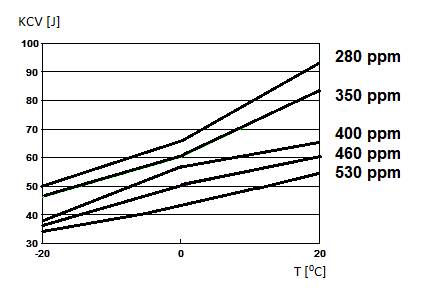
Fig. 1. The influence of oxygen on the impact
toughness properties of the WMD [5]
2. EXPERIMENTAL PROCEDURE
The aim of the investigation presented below
was to observe the common effect of nickel and oxygen on some properties of the
MAG WMD, as well as assess the effect of nickel and oxygen on the mechanical
properties of deposited metals and welds made in gas shields, involving various
typical electrode welding wires used in automotive repairs (Table 1).
Table 1
The chemical compositions of various types of
electrode welding wires
|
Wire |
PN classification |
EN classification |
AWS classification |
Main chemical
composition |
|
A |
PN ISO 14341, 4Si1 |
EN ISO 14341, 4Si1 |
AWS A5.18, ER 70S-6 |
0.08% C; 0.6% Si; 1.3% Mn; 0.01% Ni |
|
B |
SPG1 |
EN 12536, OI |
AWS A 5.2, R45 |
0.08% C; 0.3% Si; 1.1% Mn; 0.1% Ni |
|
C |
PN-88/M-69420 SPG4N |
- |
- |
0.08% C; 0.3% Si; 1.1% Mn; 1% Ni |
The WMD was prepared by the MAG welding process
(shielding gas: Ar with 15% CO2) involving microjet cooling with
various gas mixtures of Ar and CO2. The main parameters of microjet
cooling were slightly varied:
–
Cooling
steam diameter was not varied (60 µm)
–
Gas
pressure was twice varied (0.5 and 0.6 MPa)
–
Microjet
gas mixtures were substituted (various gas mixtures of Ar and CO2)
The basic material being researched was
S355J2G3 steel (typical material for truck frames and car bodies). This typical
WMD had a rather similar chemical composition in all tested cases after MAG
welding using Wire A and staining various microjet cooling gas mixtures. The
parameters of the welding process in all tested cases (for Wires A, B and C)
are presented in Table 2.
Table 2
Parameters of the
welding process
|
Arc voltage |
28 V |
|
Current |
190 A |
|
Diameter of tested wires |
1.2 mm |
|
Shielding gas |
Ar with 15% CO2 |
|
Microjet gas pressure |
0.5 and 0.6 MPa |
|
Microjet diameter |
60 µm |
|
Microjet gas mixtures |
Ar Ar with 15% CO2 Ar with 30% CO2 |
In the main, welds produced via MAG
welding with microjet cooling with various microjet gas mixtures were tested
and compared. This typical WMD had various chemical compositions regarding
welding wire choice and microjet gas mixture (Tables 3-4).
Table 3
Chemical composition of the WMD
after MAG welding using Wire A
|
Element |
Amount |
|
C |
0.09% |
|
Mn |
1.37% |
|
Si |
0.52% |
|
P |
0.014% |
|
S |
0.017% |
|
O |
290-380 ppm |
|
N |
60 ppm |
|
Ni |
0.01% |
The use of microjet
cooling after MAG welding using Wire A noticeably affected the oxygen content
of the WMD (Table 4).
Table 4
Chemical composition of the WMD after MAG
welding using Wire A
|
Gas mixture in microjet cooling micro-k |
O amount, ppm |
|
Ar |
290 |
|
Ar with 15% CO2 |
330 |
|
Ar with 30% CO2 |
380 |
This typical WMD also
had a similar chemical composition in all tested cases after MAG welding using
Wire B and staining various microjet cooling gas mixtures (Table 5).
Table 5
Chemical composition of the WMD
after MAG welding using Wire B
|
Element |
Amount |
|
C |
0.09% |
|
Mn |
1.12% |
|
Si |
0.47% |
|
P |
0.012% |
|
S |
0.017% |
|
O |
280-370 ppm |
|
N |
60 ppm |
|
Ni |
0.1% Ni |
The chemical
composition of the tested deposits was similar (Tables 3 and 5). Both deposits
had low nickel content. The use of microjet cooling after MAG welding using
Wire B also clearly affected the oxygen content of the WMD (Table 6).
Table 6
Chemical composition of the WMD after MAG
welding using Wire A
|
Gas mixture in microjet cooling micro-k |
O amount, ppm |
|
Ar |
280 |
|
Ar with 15% CO2 |
330 |
|
Ar with 30% CO2 |
370 |
The typical WMD also
had a similar chemical composition in all tested cases after MAG welding using
Wire C and staining various microjet cooling gas mixtures (Table 7).
Table 7
Chemical composition of the WMD
after MAG welding using Wire C
|
Element |
Amount |
|
C |
0.07% |
|
Mn |
0.7% |
|
Si |
0.42% |
|
P |
0.019% |
|
S |
0.013% |
|
O |
300-390 ppm |
|
N |
60 ppm |
|
Ni |
1.04% |
The third
deposit’s (C’s) chemical composition differed from the other two
(A, B), mainly in nickel, whose content changed on a logarithmic scale (Wire A;
0.01% Ni; Wire B 0.1% Ni; Wire C 1% Ni). The use of microjet cooling after MAG
welding using Wire C also noticeably affected the oxygen content in the WMD
(Table 8).
Table 8
Chemical composition of the WMD after MAG
welding using Wire C
|
Gas mixture in microjet cooling micro-k |
O amount, ppm |
|
Ar |
300 |
|
Ar with 15% CO2 |
360 |
|
Ar with 30% CO2 |
390 |
The AF amount regarding the microjet
cooling parameters (gas mixture composition and gas pressure) was precisely
analysed. In all tested cases, MAC phases (self-tempered martensite, retained
austenite, carbide) were also observed. Examples of the results of the
metallographic structure analysis are shown in Tables 9-11.
Table 9
AF and MAC phases in the WMD after MAG welding
using Wire A regarding various microjet parameters
|
Wire (Table 1) |
Gas
mixture |
Microjet gas pressure [MPa] |
AF [%] |
MAC phases [%] |
|
A |
- |
- |
41 |
3 |
|
A |
Ar |
0.5 |
52 |
3 |
|
A |
Ar + 15% CO2 |
0.5 |
54 |
3 |
|
A |
Ar + 30% CO2 |
0.5 |
52 |
3 |
|
A |
Ar |
0.6 |
53 |
2 |
|
A |
Ar + 15% CO2 |
0.6 |
58 |
3 |
|
A |
Ar + 30% CO2 |
0.6 |
55 |
2 |
The WMD gained after welding with
microjet cooling did not guarantee a high content of ferrite AF, due to the
unfavourable chemical composition of Wire A (0.08% C; 0.6% Si; 1.3% Mn; 0.01%
Ni). Si as a ferrite stabilizer occurs with too much amount, while nickel, as
an austenite stabilizer, occurs only in a trace amount. Too high a content of
Si and Mn in WMDs creates larger non-metallic inclusions, which are not
beneficial to AF nucleation.
Table 10
AF and MAC phases in the WMD after MAG welding
using Wire A regarding various microjet parameters
|
Wire (Table 1) |
Gas
mixture |
Microjet gas pressure [MPa] |
AF [%] |
MAC phases [%] |
|
B |
- |
- |
45 |
3 |
|
B |
Ar |
0.5 |
57 |
3 |
|
B |
Ar + 15% CO2 |
0.5 |
61 |
2 |
|
B |
Ar + 30% CO2 |
0.5 |
53 |
3 |
|
B |
Ar |
0.6 |
63 |
2 |
|
B |
Ar + 15% CO2 |
0.6 |
68 |
2 |
|
B |
Ar + 30% CO2 |
0.6 |
62 |
2 |
The WMD gained after welding with
microjet cooling was able to guarantee a higher content of ferrite AF than in
the previous case, due to a more favourable chemical composition of Wire B
(0.08% C; 0.3% Si; 1.1% Mn; 0.1% Ni). Si as a ferrite stabilizer occurs at a
lower level, while nickel as an austenite stabilizer occurs at a higher level.
A lower content of Si and Mn in WMDs creates smaller non-metallic inclusions,
which are very conducive to the nucleation of AF.
Table 11
AF and MAC phases in the WMD after MAG welding
using Wire A regarding various microjet parameters
|
Wire (Table 1) |
Gas
mixture |
Microjet gas pressure [MPa] |
AF [%] |
MAC phases [%] |
|
C |
- |
- |
45 |
3 |
|
C |
Ar |
0.5 |
59 |
2 |
|
C |
Ar + 15% CO2 |
0.5 |
64 |
2 |
|
C |
Ar + 30% CO2 |
0.5 |
59 |
2 |
|
C |
Ar |
0.6 |
66 |
2 |
|
C |
Ar + 15% CO2 |
0.6 |
69 |
2 |
|
C |
Ar + 30% CO2 |
0.6 |
61 |
2 |
The presence of nickel in the weld
metal blocks the conversion of austenite into a coarse ferrite, which leads to
the granulation of the ferrite grain. On analysing Tables 9-11, it is possible
to deduce that MAG welding with microjet cooling could be treated as a strong
option in all tested cases, due to the elevation of the ferrite content. It is
also shown that microjet gas pressure after MAG welding, involving all tested
gas mixtures, should always be at the level of 0.6 MPa. AF with a percentage
above 60% was only achievable after microjet cooling in the case of Deposits B
and C (Figure 2).
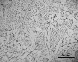
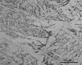
A WMD after
microjet cooling (65% AF) A WMD
without microjet cooling (45% AF)
Fig. 2. AF in various
deposits (45-65%)
In the last part of the research,
WMD impact strengths were tested at -20, 0 and 20°C and compared with the
values reported in the literature for the MMA process (Figure 1). Additionally,
it was decided to check the average size of non-metallic inclusions affecting
the nucleation of ferrite AF. Toughness was only tested in the case of
microjet-cooled deposits with a pressure of 0.6 MPa, because this parameter led
to a higher content of ferrite AF (Tables 12-14).
Table 12
Impact toughness for MAG welding
with varied microjet gases using Wire A
|
Microjet gas |
Temperature [°C] |
Impact toughness [KV, J] |
Rounded amount of non-metallic inclusions
sized 0.4-0.6 µm, % |
|
Without cooling |
- 20 |
below 47 |
15 |
|
Ar |
- 20 |
61 |
25 |
|
Ar + 15% CO2 |
- 20 |
63 |
35 |
|
Ar + 30% CO2 |
- 20 |
51 |
30 |
|
Without cooling |
0 |
54 |
15 |
|
Ar |
0 |
75 |
25 |
|
Ar + 15% CO2 |
0 |
81 |
35 |
|
Ar + 30% CO2 |
0 |
69 |
30 |
|
Without cooling |
+20 |
175 |
15 |
|
Ar |
+20 |
177 |
25 |
|
Ar + 15% CO2 |
+20 |
181 |
35 |
|
Ar + 30% CO2 |
+20 |
166 |
30 |
Microjet cooling clearly allows for
a second impact toughness class (i.e., a minimum value of 47 J at -20°C).
The highest content of smaller non-metallic inclusions corresponds to the
percentage of ferrite AF in a WMD. In addition to the positive cooling effect
of microjet cooling on the impact toughness of a WMD, the oxygen concentration in
the WMD plays an important role. The oxygen amount can be steered and precisely
controlled by the microjet process parameters.
Table 13
Impact toughness for MAG welding
with varied microjet gases using Wire B
|
Microjet gas |
Temperature [°C] |
Impact toughness [KV, J] |
Rounded amount of non-metallic inclusions
sized 0.4-0.6 µm, % |
|
Without cooling |
- 20 |
below 47 |
15 |
|
Ar |
- 20 |
67 |
25 |
|
Ar + 15% CO2 |
- 20 |
71 |
40 |
|
Ar + 30% CO2 |
- 20 |
58 |
35 |
|
Without cooling |
0 |
59 |
15 |
|
Ar |
0 |
77 |
25 |
|
Ar + 15% CO2 |
0 |
83 |
40 |
|
Ar + 30% CO2 |
0 |
77 |
35 |
|
Without cooling |
+20 |
176 |
15 |
|
Ar |
+20 |
179 |
25 |
|
Ar + 15% CO2 |
+20 |
185 |
40 |
|
Ar + 30% CO2 |
+20 |
168 |
35 |
Microjet cooling makes it even
easier to obtain a second impact toughness class (i.e., a minimum value of 47 J
at -20°C) in this case. An even higher content of small inclusions was
observed compared to the previous case (Wire A). A higher content of small
non-metallic inclusions corresponds directly to the respectively higher
percentage of ferrite AF within a WMD. Furthermore, in this case, the positive
cooling effect of microjet cooling on the impact toughness of a WMD with oxygen
concentration in the WMD was observed. This part of the investigation also
confirmed that the oxygen amount can be steered and precisely controlled by the
microjet process parameters.
Table 14
Impact toughness for MAG welding
with varied microjet gases using Wire A
|
Microjet gas |
Temperature [°C] |
Impact toughness [KV, J] |
Rounded amount of non-metallic inclusions
sized 0.4-0.6 µm, % |
|
Without cooling |
- 20 |
52 |
25 |
|
Ar |
- 20 |
71 |
40 |
|
Ar + 15% CO2 |
- 20 |
86 |
45 |
|
Ar + 30% CO2 |
- 20 |
73 |
40 |
|
Without cooling |
0 |
62 |
25 |
|
Ar |
0 |
74 |
40 |
|
Ar + 15% CO2 |
0 |
92 |
45 |
|
Ar + 30% CO2 |
0 |
75 |
40 |
|
Without cooling |
+20 |
171 |
25 |
|
Ar |
+20 |
172 |
40 |
|
Ar + 15% CO2 |
+20 |
175 |
45 |
|
Ar + 30% CO2 |
+20 |
169 |
40 |
Microjet cooling makes it even
easier to obtain a second impact toughness class (i.e., a minimum value of
47 J at -20°C) in this case. An even higher content of small inclusions was
observed, compared to the previous case (Wires A-B). The highest content of
small non-metallic inclusions (compared with A and B) corresponds directly to
the respective percentage of ferrite AF in the WMD. Furthermore, in this case,
the positive cooling effect of microjet cooling on the impact toughness of a
WMD with oxygen concentration in the WMD was observed. This part of the
investigation also confirmed that the oxygen amount can be steered and
precisely controlled by the microjet process parameters. A significant role for
nickel in terms of the plastic properties of the joint was noted. The WMD had a
second class of impact resistance, even without microjet cooling, while the
best results were obtained with the use of Wire C and microjet cooling in
comparison with the A and B deposits.
It is possible to
deduce that impact toughness in the case of a negative temperature for the WMD
is apparently affected by the type of microjet gas mixture in the cooling
injector. A gas mixture of Ar + 15% CO2 could be considered as
optimal.
3. CONCLUSIONS
The connection between processes such as MAG
welding and microjet cooling was tested with various filler materials. It was
noticed that the chemical composition of the wire and the chemical composition
of the gas mixture used for microjet cooling have an influence on WMD structure
and impact toughness. The preliminary
results validate the theoretical assumptions and indicate that it will be
possible to apply this technology in the automotive industry.
On the basis of the investigation, we
may deduce that:
–
microjet
cooling could be treated as an important element in the MAG welding process
–
microjet
cooling after welding could provide an amount of AF that is the most beneficial
phase in low-alloy steel WMDs
–
a
high amount of AF could guarantee, in relative terms, good impact toughness
properties
–
by
using microjet cooling after welding, it may be possible to steer the
metallographic structure (percentage of AF and MAC phases)
–
only
argon or helium should be used for microjet cooling after laser welding
–
a
gas mixture of Ar + 15% CO2 could be considered as optimal
References
1.
Hadryś D. 2016. “Mechanical Properties of Plug Welds After Micro-jet Cooling”.
Archives of Metallurgy and Materials 61:
1771-1775.
2.
Hadryś D. 2015. “Impact Load of Welds After Micro-jet
Cooling”. Archives of Metallurgy
and Materials 60(4): 2525-2528.
3.
Stanik Z. 2014. “Mechatronic Systems, Mechanics and
Materials”. Solid State Phenomena
210: 58-64.
4.
Evans G.M. 1994. “Microstructure and Properties of Ferritic Steel
Welds Containing Al and Ti”. Oerlikon-Schweissmitt
130: 21-39.
5.
Fornalczyk A., J. Willner, J. Cebulski, D. Pasek, M. Saternus, P. Czech.
2016. “Structure and Surface State of Different Catalytic Converters
Applied in Cars”. Fifth International
Lower Silesia-Saxony Conference “Advanced Metal Forming Processes in the
Automotive Industry (Autometform 2016)”: 327-333. 28-29 June 2016.
Wroclaw, Poland.
6.
Fornalczyk A., M. Saternus, J. Willner, M.
Fafiński, H. Kania, P. Czech. 2016. “The Results of Platinum Recovery from Metal Substrate
Catalytic Converters by Using Magneto-hydro-dynamic Pump”. 25th Anniversary International Conference on
Metallurgy and Materials “METAL 2016”: 1382-1387. 25-27 May
2016. Brno, Czech Republic. ISBN: 978-80-87294-67-3.
7.
Burdzik R., L. Konieczny, Z. Stanik, P. Folęga,
A. Smalcerz, A. Lisiecki. 2014. “Analysis of Impact of Chosen Parameters on the Wear of
Camshaft”. Archives of Metallurgy
and Materials 59(3): 957-963.
8.
Kasuya T., Y. Hashiba, S. Ohkita, M. Fuji. 2001. “Hydrogen
Distribution in Multipass Submerged Arc Weld Metals”. Science and Technology of Welding &
Joining 6(4): 261-266. DOI: 10.1179/136217101101538767.
9.
Lukaszkowicz K., L. Dobrzański, G. Kokot, P.
Ostachowski. 2012.
“Characterization and Properties of PVD Coatings Applied to Extrusion
Dies”. Vacuum 86: 2082-2088.
10.
Evans G.M. 1992. “The Effect of Micro-alloying Elements on the
Microstructure and Properties of Ferritic All-weld Metal Deposits”. IIW Doc II-A-855-92: 1-20.
11.
Mazurkiewicz D. 2010. “Tests of extendability
and strength of adhesive-sealed joints in the context of developing a computer
system for monitoring the condition of belt joints during conveyor operation”.
Eksploatacja i Niezawodnosc - Maintenance
and Reliability 3: 34-39.
12.
Krneta M., I. Samardžić, Ž. Ivandić,
D. Marić. 2018. “Joining materials by metalock repair method”.
Metalurgija 57(1-2): 142-144.
Received 14.07.2018; accepted in revised form 30.10.2018
![]()
Scientific
Journal of Silesian University of Technology. Series Transport is licensed
under a Creative Commons Attribution 4.0 International License