Article
citation information:
Gherman, L., Rotaru, C., Pearsica, M.
Electromagnetic
launch system based on a Halbach array configuration. Scientific Journal of Silesian University of Technology. Series
Transport. 2018, 101, 59-66.
ISSN: 0209-3324. DOI: https://doi.org/10.20858/sjsutst.2018.101.6.
Laurian GHERMAN[1],
Constantin ROTARU[2],
Marian PEARSICA[3]
ELECTROMAGNETIC
LAUNCH SYSTEM BASED ON A HALBACH ARRAY CONFIGURATION
Summary. The paper analyses a new configuration of an
electromagnetic launch system (EMLS) able to accelerate a 1-kg mass projectile
at a muzzle velocity of 3,000 m/s with an acceleration length of 10 m. The
analyses consist of a mathematical calculation of the value of acceleration
force necessary to achieve the project objectives. Based on these results a new
configuration of an EMLS is presented. The projectile is accelerated by the
Lorentz force where the magnetic field is created by permanent magnets made of neodymium
iron boron (NdFeB). The permanent magnets are arranged in a cylindrical Halbach
array with a uniform field inside. The copper wire coils have a special design,
which produce a large acceleration Lorentz force with a current under 1,000 A. A short comparative0 analysis
shows the advantages of this new solution compared with well-known accelerators
such as railguns and coilguns. In the next part of the paper, we present the
results of a simulation of this configuration with an interactive software package
based on the finite element method used to analyse and solve three-dimensional
electromagnetic field problems and simulate the movement of the projectile.
These results confirm the advantages of this new configuration and open the way
to test the system under laboratory conditions. At the end of the paper,
conclusions are presented. This new EMLS, based on Halbach array configuration,
can be used as a catapult for UAVs, airplanes or missiles, as a mass driver for
small satellites or as a gun, which is a better solution than railguns or
coilguns.
Keywords: Lorentz
force; Halbach array; electromagnetic catapult; finite element method
1. INTRODUCTION
In this paper we present the
theoretical results obtained during a project aimed to explore new ways to
accelerate a mass using electromagnetic energy. The objective of the project is
to accelerate a projectile with a mass of 1 kg from 0 to 3,000 m/s using 10 m
of acceleration length. According to this objective, the kinetic energy of the
projectile is:
![]() (1)
(1)
If we assume the initial speed to be
0 and the acceleration force acting on projectile to be constant, then the
value of the force is:
![]() (2)
(2)
![]() (3)
(3)
According to our project objectives,
the accelerating force acting on the projectile is a Lorentz force. The
equation of the Lorentz force, based on current intensities, which are
sometimes presented as a Laplace force, IS as follows:
![]() (4)
(4)
![]() (5)
(5)
where α is the angle between
vectors ![]() and
and![]() .
.
We assume the magnetic field to be
perpendicular to the current caring wire (α=900).
We analysed the existing railgun and
coilgun electromagnetic systems and observed a few similarities. Both use the
Lorentz force to accelerate the projectile, but the most important observation
is that the moving part is the current caring wire and the magnetic field is
created by the stator.
This configuration is, according to
the books, located where the magnetic field is static and the wire is moving.
In our project, we explore a new way where the wire is the stator, and the
projectile creates the magnetic field. The magnetic field is created by permanent magnets made of neodymium
iron boron (NdFeB) N52 with residual flux density Br=1.45-1.48 T.
For our system, we choose a ring with a Halbach array arrangement of eight
permanent magnets in order to augment the magnetic field inside the ring. For
the best results, we choose arrangements of permanent magnets to create a
uniform magnetic field inside the ring.
We expect non-uniformities of
magnetic fields created by end effects, while only taking them into
consideration during simulations. For simplicity in terms of the mathematical
calculation of the Lorentz force created, we assume the magnetic field to be
uniform and only inside the ring.
In Figure 1, we present the
simulation of the arrangement of permanent magnets and directions of
magnetization in order to obtain the uniform magnetic field inside the ring.
The Maxwell interactive software package, which uses the finite element method
(FEM), was used to analyse and solve three-dimensional electromagnetic field
problems, as well as simulate the magnetic field created by the circular
Halbach array. The residual flux density used for calculation purposes is Br=1.45
T.
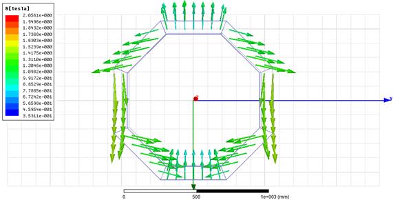
Fig. 1. Halbach array configuration
ring
In Figure 2, we present the
simulation result of a Halbach array ring made from permanent NdFeB N52
magnets. According to theory, the magnetic field lines inside the ring are
linear, starting from the bottom part of the ring to the upper part of the
ring.
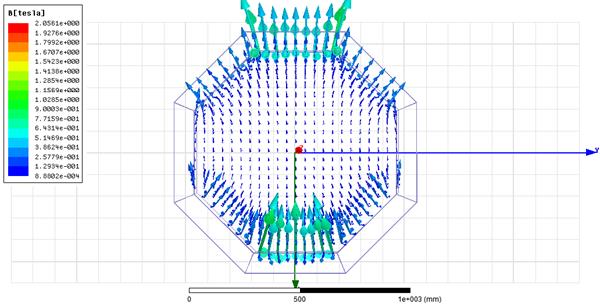
Fig. 2. Magnetic field lines inside
the Halbach array ring
As we expected, the magnetic field
density is stronger when in close range of the permanent magnets.
As the current carrying wire must be
placed in an area with a strong magnetic field, we should calculate the
dimensions of this area. Using the simulation software, we obtained the
following results.
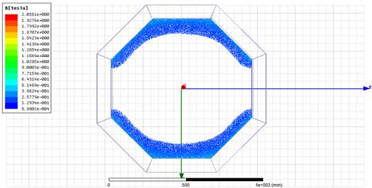
Fig. 3. The area inside the ring
with the strongest magnetic fields
According to the simulation results
displayed in Figure 3, the best area to place the current carrying wire is
inside the area shown with blue colour. After that boundary, the density of the
magnetic field drops below 0.1 T a value with no significant impact for our
project.
We used simulation software to
calculate the dimensions of the Halbach array ring in order to obtain an area
big enough to accommodate many wires. The dimensions are as follows: inner
diameter=1,000 mm, outer diameter=1,200 mm and height of the permanent
magnets=120 mm. At these dimensions, we obtained a rectangle cross-sectional
area for wires with the following dimensions: height=120 mm and length=50 mm.
In order to design the stator coil,
we should make some calculus. To keep our calculus simple, let us assume that
the magnetic field density has the same value, i.e., 1.45 T, for every wire
inside the magnetic field lines. We will obtain more precise results from
simulation. From the Lorentz force equation, we have:
![]() (6)
(6)
If we consider the length of a wire
as 1 m, then I=3.1∙106 A. This value is close to the value of
the current used in the railgun system. For our project, we are looking for a
design that uses a current with a low value. According to Equation 6, we can
lower the value of current intensity I
by increasing the value of wire length l.
As the dimensions of the Halbach array ring cannot be increased, we choose to
design a special wire coil with N
turns. The number N depends on the
size of the wire. We sought a copper wire able to sustain a fusing current calculated
per Onderdonk for 32 ms up to 1,000 A.
From the table with American wire gauges, we find AWG 19 with a diameter
of 0.912 mm. At this dimension of wire, we can accommodate N=4,600 turns in the rectangle cross-sectional area obtained via
simulation.
According to our calculus with
assumptions, the value of the necessary intensity of the current is I=673.91 A.
Theoretically, it is possible, considering the made assumptions, to achieve the
project objective using a direct current with a value of intensity less than
1,000 A.
The next step is to design a special
form of winding because we cannot use an ordinary coil. The direction of
current in the lower part of the ring must be the same as in the upper part of
the ring. In an ordinary coil, the current is in opposite direction.
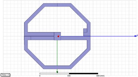
Fig. 4. The winding with the
direction of current
For our project, the winding has the
shape of the number 8 in order to obtain the same direction of current on both
sides of winding. We use the centre part of the Halbach array ring to connect
both sides of winding because, in that region, the density of the magnetic
field is at lowest level.
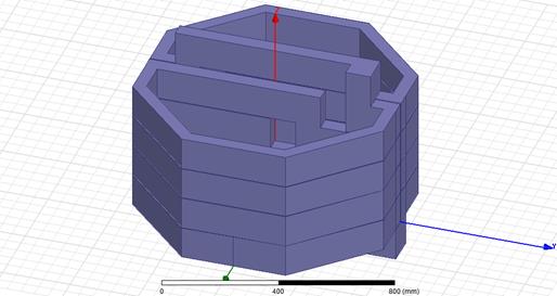
Fig. 5. The four stages of winding
For our project, we choose only four
stages of winding to simulate the acceleration length. The dimension of this
acceleration length is 0.480 m. According to the presented assumptions, we need
a speed of 657 m/s after 0.480 m to obtain a muzzle velocity of 3,000 m/s after
10 m of acceleration.
To summarize, theoretically, we need
a current with intensity of I=673.91
A to obtain an acceleration force of F=450
kN if we use the presented design. The next chapter of our paper presents the
results of simulations of this design without assumptions used for theoretical
calculation purposes.
2. SIMULATIONS
First, we built the simulation model
with the same dimensions as we used to calculate the theoretical values of
current intensity I, acceleration
force F and muzzle velocity v.
As the simulation software
calculates the Lorentz force without assumptions, we expect a slightly
different value for the intensity of current. The value of force must to be the
same as when we calculate the same muzzle velocity. The simulation model is
displayed in Figure 6.
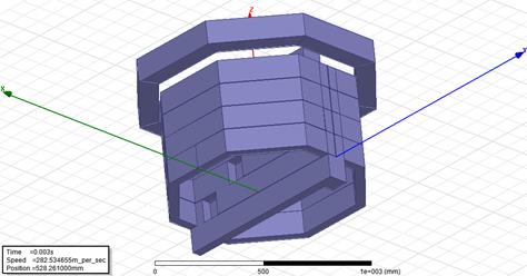
Fig. 6. The simulation model
The moving part is the Halbach array
ring, which is created inside the magnetic field. Inside the ring is the
winding, which is the acceleration part of the system. The mass of the ring is
set at 1 kg. Figure 6 presents the position of the ring after acceleration.
We simulate the movement of the
Halbach array ring for different values of intensity of the current through
wires and choose to present the values obtained for I=500 A. Figure 7 presents the variation of ring speed and the ring
position in time. The system accelerates the ring up to a maximum speed of
703.23 m/s.
The muzzle velocity of the ring is
669.85 m/s, when the bottom parts of the ring pass the limit of the
acceleration length. This value is close to the calculated value of 657 m/s.
The acceleration time is 1.44 ms. In Figure 7, the time variation of ring speed
is presented with a dotted line, while the position of the ring in time is
presented with a dashed line.
Figure 8 displays the time variation
of the Lorentz force acting on the ring with a dotted line, while the position
of the ring in time is with a dashed line. The force achieves a maximum value
of 911.37 kN when the ring is in the last stage of accelerated winding.
Fig. 7. The muzzle velocity
After that position, the value of
force decreases because the magnetic field of the Halbach array ring does not
intersect with the winding; and, when the bottom part of the ring departs from
the acceleration length, the non-uniformities of the magnetic field created by
the end effects create the deceleration force. This force has a small influence
on velocities because the ring spends only 0.07 ms in this region.
Fig. 8. The Lorentz force variation
in time
3. CONCLUSION
In this paper, we have theoretically
proven, through simulation, the possibility to obtain high muzzle velocities of
a projectile using a current with a low intensity of 500 A. As the ring is
outside the winding, it is possible to accelerate an object mechanically
connected with the ring.
If we want to decrease the
acceleration length, we can use two or more rings with two or more acceleration
windings. The object can be attached to these rings in order for them to be
accelerated. If the acceleration mass is increased, the intensity of the
current should be increased in order to obtain the desired muzzle velocity.
Acknowledgements
The paper
was prepared under the project “Microlauncher Based on a Detonation
Engine – MILADEE”, Contract 174/2017, part of the Romanian Space
Agency’s STAR programme.
References
1.
Fair H.D. 2007. “Progress in
Electromagnetic Launch Science and Technology”. IEEE Trans. on Magnetics 43(1): 93-98.
2.
Balikci A., Z. Zabar, L. Birenbaum, D. Czarkowski. 2007.
“On the Design of Coilguns for Super-velocity Launchers”. IEEE Trans. on Magnetics 43(1): 107-110.
3.
Polzin K.A., J.E. Adwar, A.K. Hallock. 2013.
“Optimization of Electrodynamic Energy Transfer in Coilguns with
Multiple, Uncoupled Stages”. IEEE Trans. on Magnetics 49(4): 1453-1460.
4.
Wenbo L., W. Yu, G. Zhixing, Y.
Zhongming, C. Weirong. 2013. “Connection Pattern Research and
Experimental Realization of Single Stage Multipole Field Electromagnetic
Launcher”. IEEE Trans. on Plasma
Science 41(11): 3173-3179.
5.
Su Z. et
al. 2015. “Investigation of Armature Capture Effect on
Synchronous Induction Coilgun”. IEEE Transactions on Plasma Science
43(5): 1215-1219. DOI: 10.1109/TPS.2015.2410302.
6.
Abdalla M.A., H.M. Mohamed. 2016. “Asymmetric Multistage
Synchronous Inductive Coilgun for Length Reduction, Higher Muzzle Velocity, and
Launching Time Reduction”. IEEE Transactions on Plasma Science
44(5): 785-789. DOI: 10.1109/TPS.2016.2543500.
7.
Perotoni M.B., M. Mergl, V.A. Bernardes. 2017. “Coilgun Velocity
Optimization with Current Switch Circuit”. IEEE Transactions on
Plasma Science 45(6): 1015-1019. DOI: 10.1109/TPS.2017.2700789.
Received 23.07.2018; accepted in revised form 02.11.2018
![]()
Scientific
Journal of Silesian University of Technology. Series Transport is licensed
under a Creative Commons Attribution 4.0 International License