Article
citation information:
Droździel, P., Popovych, P., Vitenko,
T., Shevchuk, O., Zolotyi, R., Kononchuk, O. Prediction of transport
vehicles’ durability with consideration of corrosive surface cracks
propagation in structural elements. Scientific
Journal of Silesian University of Technology. Series Transport. 2018, 101, 47-57. ISSN: 0209-3324. DOI: https://doi.org/10.20858/sjsutst.2018.101.5.
Paweł DROŹDZIEL[1],
Pavlo POPOVYCH[2],
Tetiana VITENKO[3],
Oksana SHEVCHUK4, Roman ZOLOTYI5, Oleksandr KONONCHUK6
PREDICTION OF
TRANSPORT VEHICLES’ DURABILITY WITH CONSIDERATION OF CORROSIVE SURFACE
CRACKS PROPAGATION IN STRUCTURAL ELEMENTS
Summary. Support frameworks of transport
vehicles operate under varying terrain conditions under the influence of
extreme climate and corrosive environments. When transporting cargo, dust is
deposited on the surface of metal structures. The combination of dust and
moisture creates an aggressive environment resulting in intense corrosion
damage. The damage is caused by the defects of corrosion pitting, which occur
on the surface and transform into corrosion cracks. Based on energy approaches,
with the application of well-known results for the mathematical description of
electrochemical reactions and the principles of fragile fracture mechanics, an
analytical model of durability is proposed for the first time. The model
determines the residual life of maximum loaded elements of undercarriages with
surface cracks under the action of dynamic loads and corrosive environments.
For this case, a set of mathematical relations in the form of a non-linear
differential equation was developed, as well as the initial and final
conditions for determining the life of vehicles’ structural elements with
corrosive surface cracks. The analytical model implementation is proven by
solving the problem of determining the residual life of a vehicle’s
element, i.e., a steel plate, weakened by a semi-elliptical surface crack,
which is under the action of dynamic loads in a 3% sodium chloride solution.
The insignificant increase in the crack’s initial size is proven to
greatly reduce the period of its subcritical growth. The developed model was
applied to define the residual life of thin-walled elements of structures with
surface cracks.
Keywords: elements of structures with surface cracks; kinetic diagram of
corrosion-fatigue crack propagation; period of subcritical growth of
corrosion-fatigue cracks; durability of vehicle
1. INTRODUCTION
Transport vehicles operate under
varying terrain conditions involving extreme climate and corrosive
environments. For this reason, their main bearing elements are mainly made of
steel. In most vehicular structures, the base unit is a frame that contains up
to 40% of the steel intensity of the vehicle and significantly affects its
life, with the key factor affecting durability being the damage to the frame
caused by cracks and corrosion [1]. Factoring in the volumes of fertilizers
transportation (about 2% of all cargo in Ukraine [18]), it is rational to
account for the influence of aggressive environments acting upon metal
materials of vehicles. When transporting fertilizers, poisonous chemicals and
other aggressive agrarian products, the dust of these substances is deposited
on the structure surface. The combination of dust and moisture creates an
aggressive environment, which, together with the operating loads (usually
cyclic), leads to intense corrosion damage, in particular, by propagating
surface corrosion-fatigue cracks in elements of vehicular structures [1-8, 14-22].
The corrosion processes rate is known to be a function of the aggressiveness
and duration of the environment effect, the air temperature, the metal surface
state (composition and structure of the protective film), the chemical
composition of the metal, the presence of mechanical stresses, structural
features (welds, bolt and rivet joints), and the combination of elements
creating cavities or cracks, in which moisture condenses. Contamination of
vehicles’ metal structure surfaces intensifies corrosion, while, in
combination with moisture, it can create an electrochemical environment that
causes more intensive corrosion processes. Corrosion is the most dangerous
phenomenon for parts operating under cyclic loads (springs, body springs, axes,
shafts etc.), whose lifetime is often reduced by 40-60% because of fatigue
failure [1,8,12,15,21]. Based on part failure analyses, fracture initiation
occurs due to the ulcers caused by corrosion and pitting, with the ulcers
transferring into surface corrosion cracks, which adversely affect vehicle
reliability [1,12,13,15,21].
2. MATERIAL AND METHODS
A three-dimensional body is
considered as an element of the vehicle metal structure. A flat surface crack
with a contour of a length L and an initial area S0 weakens the
body, which is loaded cyclically with the amplitude forces p. There is a corrosive-aggressive environment in the crack cavity
(Figure 1). Outer tensile loads are applied so that the stress-strain state in
this body is symmetrical, relative to the placement of a crack plane.
Fig. 1. Corrosion-fatigue cracks in
the vehicle frame, a classical body scheme of loading a body with a flat
surface crack
Hence, it is described in the
vicinity of its peak exclusively by the stress intensity factor of the first
kind ![]() . The task is to determine the
time or number of load cycles
. The task is to determine the
time or number of load cycles ![]() , in which the body, as an
element of the vehicle metal structure, will fracture.
, in which the body, as an
element of the vehicle metal structure, will fracture.
To solve this problem, a
mathematical model is developed: differential equations with initial and finite
conditions that describe this process. The assumption that the crack increases
continuously from the original area S = S0
to the final one S = S* is
correct, since it is well known that the real development of the
corrosion-fatigue crack is accompanied by jumps in the value ![]() in relatively large time intervals
in relatively large time intervals ![]() (
(![]() , where
, where ![]() is the number of load cycles
during an elementary jump of the crack and T
is the cycle period). Thus, the dependence for determining the growth rate of
the crack will be written approximately.
is the number of load cycles
during an elementary jump of the crack and T
is the cycle period). Thus, the dependence for determining the growth rate of
the crack will be written approximately.
![]() (1)
(1)
Similar to [8-11], the energy
balance equation for this non-equilibrium process is:
![]() (2)
(2)
where Q =
const is the value of thermal energy, A is the work of external forces, and
W is the energy of body deformation after the propagation of the crack
area by the value ![]() , written according to [8-11].
, written according to [8-11].
![]() (3)
(3)
where: ![]() is the elastic component W;
is the elastic component W; ![]() is a part of the work of plastic
deformations in the prefracture area, which depends exclusively on the area of
the crack l;
is a part of the work of plastic
deformations in the prefracture area, which depends exclusively on the area of
the crack l; ![]() is a part of the work of plastic
deformations caused by external forces, which is allocated at a constant crack
area during the incubation period of its jump preparation and depends only on
time t;
is a part of the work of plastic
deformations caused by external forces, which is allocated at a constant crack
area during the incubation period of its jump preparation and depends only on
time t; ![]() is the work of plastic deformations
during body unloading and compression of the prefracture area, which depends
exclusively on and generates by the body itself; Γ is the energy of body destruction, which depends on the
crack area, characteristics of the environment and t; Q is the released
thermal energy during body destruction, which is considered a relatively small
value and neglected in calculations; and K
is the kinetic energy, which in
this case is also considered a small value.
is the work of plastic deformations
during body unloading and compression of the prefracture area, which depends
exclusively on and generates by the body itself; Γ is the energy of body destruction, which depends on the
crack area, characteristics of the environment and t; Q is the released
thermal energy during body destruction, which is considered a relatively small
value and neglected in calculations; and K
is the kinetic energy, which in
this case is also considered a small value.
Considering the above and
differentiating the components of the energy balance equation (2) by the number
of load cycles N, an equation for the
velocities balance of the energy components change is deduced:
![]() (4)
(4)
The components of the dependence for
determining the energy of deformation are complex functions in S and N [9-10], while the area also implicitly depends on N. Thus, while substituting 3 for 4, the
following formula is developed:
![]() (5)
(5)
Based on (5), the rate value of the
crack area changes during its propagation:
![]() (6)
(6)
Based on [10, 11], (6) is written
thus:
![]() (7)
(7)
To complete this mathematical model,
in analogy with [10-11], respectively, the initial and final conditions are
added to 7:
![]() (8)
(8)
![]()
where the critical value of the crack area ![]() and
and ![]() are determined [10-11].
are determined [10-11].
![]() (9)
(9)
Thus, the kinetic equation (7) with
the conditions (8-10) is a mathematical model for the study of subcritical
growth in the corrosion-fatigue crack in the elements of vehicles’
structures on symmetrical loading.
The realization of the mathematical
problem (7-10) for specific cases is associated with significant mathematical
difficulties. Therefore, the problem solution is simplified in analogy with
[11]. Consequently, a half-space with a plane surface crack, into which the
corrosive environment enters, is stretched cyclically at endlessly distant
points, which are uniformly distributed by the amplitude σ and directed perpendicular to the plane of the crack
placement. According to the results [11-12], the growth rate V of the crack under consideration in
its straightforward propagation is related to the parameters of the
stress-strain state in the prefracture area by the ratios:
![]()
 (10)
(10)
Similar to the [11-12], the case, in
which destruction occurs under the action of cyclic loads and a
corrosive-aggressive environment in one plane of a three-dimensional body, is
considered. Since the crack propagates along the normal to its periphery, the
movement in the time period ![]() of the arbitrary point M of the crack periphery runs towards
the normal (Figure 2).
of the arbitrary point M of the crack periphery runs towards
the normal (Figure 2).
![]()
Hence, the growth in the radius
vector ![]() of the polar system
of the polar system ![]() (Figure 2) is written thus:
(Figure 2) is written thus:
Fig. 2. Scheme for the local growth
of a flat corrosion-fatigue crack [11]
![]() (11)
(11)
where ![]() is the angle between the direction of the
radius vector
is the angle between the direction of the
radius vector ![]() and the normal to the crack periphery MM’. Based on the analysis of
geometric construction, in Figure 2, we get [11-12]:
and the normal to the crack periphery MM’. Based on the analysis of
geometric construction, in Figure 2, we get [11-12]:
 (12)
(12)
Substituting 14 for 13 and moving to
the boundary at![]() , the velocity is:
, the velocity is:
 (13)
(13)
In addition, based on 11 and 15, to
find an unknown function ![]() , the differential equation is
deduced:
, the differential equation is
deduced:
 (14)
(14)
At initial and final terms:
 (15)
(15)
In this case, Relations 16-17 define
the problem for determining the kinetics of propagation and the period ![]() of
subcritical growth in the surface crack under study (residual life) in the
metal structure element of the vehicle. To determine
of
subcritical growth in the surface crack under study (residual life) in the
metal structure element of the vehicle. To determine ![]() , the condition (Irwin’s
criterion [4]) is added:
, the condition (Irwin’s
criterion [4]) is added:
![]() (16)
(16)
To realize the mathematical model
(16-18), the following approximate approach [12-13] is proposed, according to
which the change in the area of a moving crack of the considered configuration
is approximately the same as for a semicircular crack of a radius ![]() of
a plane initial area. The rate of periphery propagation of such a crack is
defined by the constant in all its points for the maximum value
of
a plane initial area. The rate of periphery propagation of such a crack is
defined by the constant in all its points for the maximum value ![]() . Therefore, an error in the
resulting residual life
. Therefore, an error in the
resulting residual life![]() occurs in increasing the value
of the durability reserve, that is, 16 is simplified to:
occurs in increasing the value
of the durability reserve, that is, 16 is simplified to:
 (17)
(17)
At initial and final terms:
 (18)
(18)
where ![]() for a half-space with a surface
semicircular crack under tension is determined based on [13]:
for a half-space with a surface
semicircular crack under tension is determined based on [13]:
![]() (19)
(19)
By substituting 21 for 19 and
integrating it under the relevant conditions (20), to determine the period ![]() of subcritical growth in the
corrosion-fatigue crack of the initial area
of subcritical growth in the
corrosion-fatigue crack of the initial area ![]() in the half-space, the following
dependence is developed:
in the half-space, the following
dependence is developed:
 (20)
(20)
where ![]()
3. RESULTS
To study
the implementation of the proposed model, the case associated with the case of
individual soils [14] is considered: the development of a surface corrosion
crack in a vehicle’s metal structure element made of steel (17G1C), in a
corrosive environment (3% solution of sodium chloride). The load frequency is
assumed to be 1 Hz, which is included in the asymmetry of the cycle ![]() with the loading amplitude
with the loading amplitude ![]() . The critical size of the crack in
this case is
. The critical size of the crack in
this case is ![]() , and the kinetic diagram of the
corrosion-fatigue crack growth is described by the ratio [10-11]:
, and the kinetic diagram of the
corrosion-fatigue crack growth is described by the ratio [10-11]:
 (21)
(21)
Substituting the given data in 22 and integrating the sub-integral
integer numerically, the value![]() is derived
is derived
![]() cycles (22)
cycles (22)
Based on the above (Figure 3), a dependency
graph of the period of subcritical growth in the corrosion-fatigue cracks on
the size of the crack ![]() is developed. Consequently, as
seen in Figure 3, the reduction of the crack size dramatically increases the
period of subcritical growth of the crack
is developed. Consequently, as
seen in Figure 3, the reduction of the crack size dramatically increases the
period of subcritical growth of the crack ![]() .
.
The residual life of the vehicle’s metal
structure element concerns a plate with a surface semi-elliptic crack. Let us
consider the steel plate 17G1C, with the thickness ![]() weakened by a surface
semi-elliptic crack, and a0
and bo (bo>ao) as the semi-axes, in which a 3% solution of sodium
chloride falls (Figure 4) [14]. It is assumed that the plate is stretched at
infinitely distant points perpendicular to the plane of crack propagation by
evenly distributed cyclic forces of the amplitude with a 1-Hz frequency and cycle
asymmetry
weakened by a surface
semi-elliptic crack, and a0
and bo (bo>ao) as the semi-axes, in which a 3% solution of sodium
chloride falls (Figure 4) [14]. It is assumed that the plate is stretched at
infinitely distant points perpendicular to the plane of crack propagation by
evenly distributed cyclic forces of the amplitude with a 1-Hz frequency and cycle
asymmetry![]() . The task is to determine the number of load cycles
. The task is to determine the number of load cycles ![]() , in which the corrosion-fatigue crack periphery will become tangent to its
opposite surface. Therefore, the kinetic diagram of the corrosion-fatigue crack
propagation in the plate material is described by analytic dependence (23).
, in which the corrosion-fatigue crack periphery will become tangent to its
opposite surface. Therefore, the kinetic diagram of the corrosion-fatigue crack
propagation in the plate material is described by analytic dependence (23).
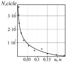
Fig. 3. Dependence of
residual life ![]() on the initial size of a surface crack
on the initial size of a surface crack ![]()
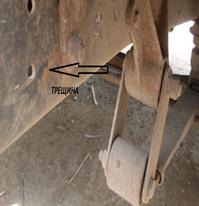
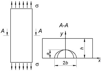
Fig. 4.
Corrosion-fatigue crack of the vehicle’s carrier [23] and the scheme of
loading the plate with a surface semi-elliptic crack [15]
The solution is performed by
the method of equivalent areas [12-13]. According to this method, the change in
area, due to the corrosion-fatigue crack propagation of the considered
configuration, will be approximated as for a semicircular crack with a radius ![]() of
the same initial area. The propagation velocity of its periphery points is
assumed to be approximately the same. The crack periphery in a plate restricts
an area, which is equal to a semi-elliptical real crack, on account of a
semicircular radius
of
the same initial area. The propagation velocity of its periphery points is
assumed to be approximately the same. The crack periphery in a plate restricts
an area, which is equal to a semi-elliptical real crack, on account of a
semicircular radius ![]() .
Therefore, to replace this problem with a model, the maximum value of the SIF
along this chosen circular is [13]:
.
Therefore, to replace this problem with a model, the maximum value of the SIF
along this chosen circular is [13]:
![]() (23)
(23)
Substituting 25 for 23 in order to
determine the period ![]() , the following equation is deduced:
, the following equation is deduced:
 (24)
(24)
At initial and final terms:
![]() ,
, ![]() ;
; ![]() ,
, ![]() .
.
To determine ![]() , (26)
integrates within the given initial and final conditions. As a result:
, (26)
integrates within the given initial and final conditions. As a result:
 (25)
(25)
Numerical analysis of the expression
is performed at ![]() 0.04 m,
0.04 m, ![]() 70MPa. As a result, 27 is written as:
70MPa. As a result, 27 is written as:
 (26)
(26)
Based on
28, the dependency graph of the residual life of the plate with a surface
corrosion-fatigue crack in the initial size ![]() (Figure 5) is developed.
Therefore, a small increase in the initial size
(Figure 5) is developed.
Therefore, a small increase in the initial size ![]() significantly reduces the period
of the surface corrosion-fatigue crack growth
significantly reduces the period
of the surface corrosion-fatigue crack growth![]() in the vehicle’s metal
structure.
in the vehicle’s metal
structure.
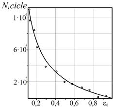
Fig. 5. Dependence of the period on ![]() of a surface corrosion-fatigue crack
growth in the initial size
of a surface corrosion-fatigue crack
growth in the initial size ![]()
4. CONCLUSIONS
For the case of the action of
variable loads in aggressive environments on vehicles’ structures with
corrosive surface cracks, a mathematical model is developed: the non-linear
differential equation in partial derivatives and the initial and final terms
for calculating the period of subcritical growth of corrosion-fatigue cracks in
these elements of vehicles. The effective method for an approximate solution of
this analytic problem is substantiated. The implementation of the mathematical
model is demonstrated using the example of calculating the durability of the
vehicle’s element as the residual life of a plate made of 17G1S steel,
which is weakened by a surface semi-elliptic crack under the action of cyclic
loads in a solution of sodium chloride. A slight increase in the initial sizes
of corrosive surface cracks is found to significantly reduce the durability of
vehicles’ structural elements.
References
1.
Severnyi А.Ye. 1993. Stability and corrosion protection of agricultural machinery.
Moscow: State Research and
Technological Institute.
2.
Pohmurskyi V.I., М.S. Khoma. 2008. Corrosive fatigue of metals and alloys. Lviv: Spolom.
3.
Romaniv О.N., S.Ya. Yarema, G.N. Nikiforchyn, N.А. Makhutov,
М.М. Stadnyk. 1990. Fatigue and cyclic crack resistance of structural materials. Kiev: Naukova
Dumka.
4.
Cherepanov G.P. 1974. Mechanics of brittle failure. Moscow:
Nauka.
5.
Dmytrah І.М., V.V. Panasiuk. 1999. Influence of corrosive media on local
destruction of metals near stress concentrators. Liviv: PMI NASU.
6.
Korneyenko S.V., О.М. Korbutiak. 2008. „Resources
of underground geological space of Ukraine”. Geology 43: 51-53.
7.
Korneyenko
S., О.M. Korbutiak. 2009.
„Problems of the influence of soil environment on corrosion of main gas
pipelines of Ukraine”. Geology
46: 42-43.
8.
Maltseva G. N. 2000. Corrosion and protection of equipment against corrosion. Penza.
9.
Andreykiv O.Ye., М.V. Кіt. 2006. Determination
of residual durability of thin-walled elements of structures at two-axis loads. Physical-Chemical Mechanics of Materials
1: 11-16.
10.
Andreykiv O.Ye., М.V.
Кіt. 2006. „Determination
of the period of subcritical growth of cracks in the elements of structures at
their two-frequency loads”. Machine Science 2: 3-9.
11.
Andreykiv O.Ye., N.B. Sas. 2008. “The
subcritical growth of a flat crack in a three-dimensional body at high
temperature creep”. Physical-Chemical Mechanics of Materials
2: 19-26.
12.
Andreykiv O.Ye., А.I. Darchuk. 1992. Fatigue failure and durability of structures.
Kiev: Naukova Dumka.
13.
Directory
of stress intensity coefficients. 1990. Mir: Murakami.
14.
Tsyrulnyk O.T., D.Yu. Petryna, M.I. Hredil. 2006.
“The fracture peculiarities of trunk pipeline steels after their long
term service”. Proceedings of the
international conference on Crack paths (CP 2006). Paper No 61. Parma,
Italy, 14th-16th September 2006.
15.
Shchurin К.V. 1994. Forecasting and increasing the fatigue life of the bearing systems of
agricultural tractor means. Dissertation of Doctor of Science
(Engineering). Orenburg.
16.
Figlus T. 2015. The
application of a continuous wavelet transform for diagnosing damage to the
timing chain tensioner in a motorcycle engine. Journal
of Vibroengineering17(3):
1286-1294. ISSN: 1392-8716.
17.
Koziol M., T. Figlus. 2017. Evaluation of
the failure progress in the static bending of GFRP laminates reinforced with a
classic plain-woven fabric and a 3d fabric, by means of the vibrations analysis.
Polymer Composites 38(6): 1070-1085.
DOI: 10.1002/pc.23670.
18.
Ukrayina u tsyfrakh. Statystychnyy
zbirnyk. Vidpovidal'nyy za vypusk O.A. Vyshnevs'ka. Za redaktsiyeyu: I.Ye. 2017.
Vernera. Kyyiv: Derzhavna sluzhba statystyky Ukrayiny. [In Ukrainian: Ukraine on numbers. Static zbirnik.
Edited by I.E. Werner. Kiyiv:
State Statistics Service].
19.
Kosicka
E., E. Kozłowski, D. Mazurkiewicz. 2015. „The use of stationary
tests for analysis of monitored residual processes”. Eksploatacja i Niezawodnosc – Maintenance and Reliability
17(4): 604-609. DOI: http://dx.doi.org/10.17531/ein.2015.4.17.
20.
Maruschak
Pavlo, Sergey Panin, Ilya Vlasov, Olegas Prentkovskis, Iryna Danyliuk. 2015.
„Structural levels of the nucleation and growth of fatigue crack in
17Mn1Si steel pipeline after long-term service”. Transport 30(1): 15-23.
21.
Maruschak
P., Poberezhny L., Pyrig T. 2013. “Fatigue and
brittle fracture of carbon steel of gas and oil pipelines”. Transport 28(3): 270-275.
22.
Figlus Tomasz, Marcin Stańczyk. 2014. “Diagnosis of the wear
of gears in the gearbox using the wavelet packet transform”. Metalurgija
53(4): 673-676. ISSN: 0543-5846.
Received 19.07.2018; accepted in revised form 11.10.2018
![]()
Scientific
Journal of Silesian University of Technology. Series Transport is licensed
under a Creative Commons Attribution 4.0 International License