Article
citation information:
Brumercik, F., Lukac, M., Majchrak,
M., Krzysiak, Z., Krzywonos, L. Teeth geometry and contact pressure calculation of
external cycloidal gears. Scientific
Journal of Silesian University of Technology. Series Transport. 2018, 101, 27-35. ISSN: 0209-3324. DOI: https://doi.org/10.20858/sjsutst.2018.101.3.
Frantisek
BRUMERCIK[1], Michal LUKAC[2], Maros MAJCHRAK[3], Zbigniew KRZYSIAK[4], Leszek KRZYWONOS[5]
TEETH GEOMETRY AND
CONTACT PRESSURE CALCULATION OF EXTERNAL CYCLOIDAL GEARS
Summary.
Cycloidal (also called epicyclical or convex-concave) gears are used less often
than common involute gears, which are very easy to manufacture and can be
modified by corrections to the gear profile. Cycloidal gears are very sensitive
to the proper axial distance between the pinion and the gear. The main
advantage of convex-concave gears is the lowering of the contact pressure due
to teeth flanks meshing and also the lowering of the slide ratios compared to
involute gears. The calculation of the selected geometrical parameters and the
contact pressure between the teeth flanks of the cycloidal gearing is described
in the presented article.
Keywords: gear; cycloidal; convex-concave;
geometry; contact pressure
1. INTRODUCTION
The mathematical model of convex-concave
gearing is the basis of the geometry model calculation and as described in
detail in [1]. The determination of the geometric parameters in the
gear’s teeth flanks is based on the equations evaluated from the shape of
the path of contact. The general path of contact starting at point A and ending
at point E for this type of gearing is presented in Figure 1.
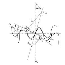
Fig.
1. Path of contact of convex-concave gearing
The arcs of the path of contact are
circular arcs defined by their radii rkh for the upper one and rkd
for the lower one. The centres of the arcs Skh and Skd,
which lie on the common link passing through the contact inflection point C,
are defined by the coordinates xSkh, ySkh and xSkd,
ySkd in the coordinate system with the origin located in contact
point C.
Points A and
E are limiting points of the teeth gear mesh. Their position can also be
projected onto the teeth flanks’ cycloidal curves in both meshing gears,
which limits the working area of the teeth flanks [2, 3].
2. GEOMETRY OF THE
TEETH FLANKS
The
cycloidal teeth can generally be understood as any teeth whose tooth flank
forms a curve with a convex and a concave part. Such teeth are present when the
contact path is a so-called S-curve, as defined above [4]. Deriving the form of
the correctly mating profiles of a cycloidal gearing can be done using basic
knowledge of differential geometry and the direct application of the
fundamental law of gearing [5]. The main goal of this method is to determine
the relation between the
pressure angle at various points of the path of contact α and the angle of the gear
rotation between pressure angles of two arbitrary points φr (α) (Figure 2).
Fig.
2. Relation between the angles α
and φr:
1)
path of contact; 2) tooth flank profile; 3) tooth flank profile evolute
The relation is defined by Equation 1:
 , (1)
, (1)
where:
α -
the pressure angle at various points of the path of contact
φr (α) - the angle of
the gear rotation between pressure angles of two arbitrary points
and the signs are
defined as positive for the upper part and negative for the lower part of the
path of contact.
The parametric
equations of the gear tooth flank profiles, obtained by the coordinates’
transformation of the path of contact’s compound of two circular arcs,
are defined by the Equation 1.
![]() , (2)
, (2)
![]() . (3)
. (3)
The x and y coordinates are defined for the coordination system with the
origin aligned to the point of rotation of the pinion O1 and the
gear O2. The upper signs in the equations stand for the upper part
of the path of contact (indexed with h) and the lower signs in the equations
stand for the lower part of the path of contact (indexed with d).
The division of the
contact path into an upper and a lower part requires the division of all geometric
and other cycloidal gear pair parameters into analogous parts, which will be
defined according to the corresponding parts of the contact path curve [6].
It is suitable to
derive Equations 2 and 3 into a form that defines the addendum (indexed with a)
and the dedendum (indexed with f) of the gear teeth separately.
2.1. Pinion
The
coordinates of the pinion 1 addendum flank curve are based on the upper part of
the contact path arc dimension, according to the following equations:
![]() , (4)
, (4)
![]() . (5)
. (5)
The coordinates of the pinion 1 dedendum flank curve
is based on the lower part of the contact path arc dimension, according to the
following equations:
![]() , (6)
, (6)
![]() . (7)
. (7)
2.2. External gear
The tooth flank profile coordinates of the external
gear 2 can be derived from the equations defined for the pinion 1 considering
the gear ratio between them, which is defined as:
![]() . (8)
. (8)
The coordinates of the external gear addendum flank
curve are based on the lower part of the contact path arc dimension, according
to the following equations:
![]() , (9)
, (9)
![]() . (10)
. (10)
The coordinates of the external gear dedendum flank
curve is based on the upper part of the contact path arc dimension, according
to the following equations:
![]() , (11)
, (11)
![]() . (12)
. (12)
3. SINGLE MESH POINTS
The coordinates of the single mesh
points B and D are obtained by solving Equation 1, while considering the angle turns φrAD and φrEB
to be equal to the angle defined by the pinion tooth pitch [1].
![]() , (13)
, (13)
![]() . (14)
. (14)
The pressure angles αB and αD in the single mesh points B and D are
calculated using the following transcendental equations:
 , (15)
 . (16)
The single mesh points are important for the
definition of the normal force value, which is divided between two pairs of
meshing teeth at the path of contact curves AB and CD (Figure 1).
4. CONTACT PRESSURES
The contact pressure
calculation is based on Hertz contact theory [3,7], which is also defined for
the upper as well as the lower parts of the path of contact by the following
equations:
![]() , (17)
, (17)
![]() . (18)
. (18)
The normal forces at
the contact points A to C (F1h)
and at C to E (F1d) are
calculated at the pinion 1, loaded by the input torque Mk1, as follows:
![]() (19)
(19)
![]() (20)
(20)
The reduced Young’s modulus of the
pinion and gear material is a part of the material coefficient ZE, which is calculated by
Equation 8 [9].
 , (21)
where:
μ1, 2 - Poisson’s
ratios of the contact pair materials,
E1, 2 - Young’s moduli
of the contact pair materials.
The
reduced radius of curvature ρred
is calculated according to these equations:
![]() , (22)
, (22)
![]() . (23)
. (23)
The
radii of curvature of the pinion 1 addendum (a) and dedendum (f) are defined
as:
![]() , (24)
, (24)
![]() . (25)
. (25)
The
radii of curvature of the gear 2 addendum and dedendum are defined as:
![]() , (26)
, (26)
![]() . (27)
. (27)
5. CALCULATION OF SELECTED GEAR PAIR VALUES
The selected
gear pair with the module m = 4 mm
and the teeth number z1 =
16 and z2 = 24 will
represent the application of all derived equations into a model of cycloidal
gear pair geometry and the distribution of contact pressure by meshing of the
gear teeth.
The geometry
is influenced by the module m, the
number of teeth z, the radii of the
contact path arcs rkh and rkd, and the pressure angle
at the point C αC. The
convex-concave condition is satisfied, if there is a valid inequation [1].
![]() . (28)
. (28)
The radii of
the contact path arcs in the symmetric arrangement within the selected gear
pair were defined as rkh =
rkd = 8 mm and the
pressure angle in the point C as αC
= 20°, which satisfies the inequation (28). The geometry of the selected
gear pair is presented in Figure 3.
The contact
pressure between the pinion and the gear at the tooth flanks is calculated by
the unit values of the torque Mk1,
the speed w1 and the gear
tooth flank width l, all of which are
defined as being equal to 1. The gears are considered from steel with
Poisson’s ratios μ1
= μ2 = 0.3 and
Young’s moduli E1 = E2 = 210000 MPa. The Hertz
pressure distribution, as projected onto the pinion and gear teeth flanks, is
presented in (Figure 4).
The contact
Hertz pressure pH between the pinion and
the gear, up to the angle of the pinion rotation between the pressure angles of
two arbitrary points φr1 (α), is shown in Figure 5.
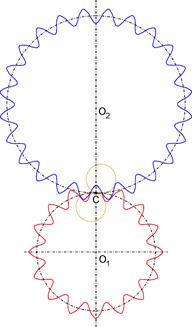
Fig.
3. Geometrical model of the gear pair with cycloidal teeth flanks
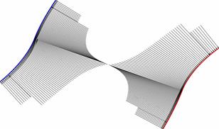
Fig.
4. Hertz pressure distribution projected onto the gear (left) and pinion
(right) teeth flanks
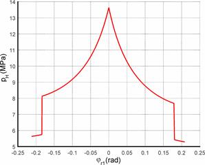
Fig.
5. Hertz’s pressure pH
up to angle φr1
6. CONCLUSION
The article
presents a possible approach for modelling cycloidal gear teeth flanks based on
the path of contact curves. The calculation of the maximum contact pressure at
various points of the gear pair teeth flanks is also defined. The calculation
of a selected gear pair is performed by the unit values of the torque, speed
and tooth flank width. The obtained model is fully parametric and allows us to
calculate the Hertz pressures for various combinations of the characteristic
gear pair values, such as the module, the teeth numbers, the pressure angle in
the contact point C and the radii of the path of contact curve. The change in
the characteristic gear pair values enables us to pursue further research on
their influence on Hertz pressure values [9,10,12].
Acknowledgement
The research
is supported by the Cultural and Educational Grant Agency of the Ministry of
Education, Science, Research and Sport of the Slovak Republic under Project No.
046ŽU-4/2018.
References
1.
Veres Miroslav,
Miroslav Bosansky, Jan Gadus. 2006. Theory
of convex-concave and plane cylindrical gearing. Bratislava: Slovak
university of technology. ISBN 80-250227-2451-3.
2.
Puškár
M., M. Fabian, T. Tomko. 2018. „Application of multidimensional
statistical model for evaluation of measured data obtained from testing of the
HCCI engine prototype”. Diagnostyka
19(1): 19-24. DOI: http://dx.doi.org/10.29354/diag/78349.
3.
Sarkan B., O. Stopka, Ch. Li. 2017. “The issues of measuring the
exterior and interior noise of road vehicles”. Komunikacie 2: 50-55.
4.
Glowacz Adam, Zygfryd Glowacz. 2017. „Diagnosis of the three-phase
induction motor using thermal imaging”. Infrared physics & technology 81: 7-16. ISSN 1350-4495. DOI:
https://doi.org/10.1016/j.infrared.2016.12.003.
5.
Glowacz Adam, Zygfryd Glowacz. 2017.
„Diagnosis of stator faults of the single-phase induction motor using
acoustic signals”. Applied Acoustic
117A: 20-27. ISSN 0003-682X. DOI: https://doi.org/10.1016/j.apacoust.2016.10.012.
6.
Figlus Tomasz, Mateusz
Koziol. 2016. „Diagnosis of
early-stage damage to polymer - glass fibre composites using non-contact
measurement of vibration signals”. Journal of Mechanical Science and Technology 30(8): 3567:3576. ISSN 1738-494X. DOI: 10.1007/s12206-016-0717-1.
7.
Skrucany Tomas, Branislav Sarkan, Tomasz Figlus, et al.
2017. „Measuring of noise emitted by moving
vehicles”. MATEC
Web of Conferences 107: 00072. ISBN:
978-1-5108-4114-7. DOI: https://doi.org/10.1051/matecconf/201710700072
8.
Kohar Robert,
Slavomir Hrcek. 2014. „Dynamic Analysis of a Rolling Bearing Cage with
Respect to the Elastic Properties of the Cage for the Axial and Radial Load
Cases”. Communications –
Scientific Letters of the University of Zilina 16 (3A): 74-81. ISSN
1335-4205.
9.
Faturik Lukas, Libor Trsko, Slavomir Hrcek,
Otakar Bokuvka. 2014. „Comparison
of structural design in high and ultra-high cycle fatigue regions”. Transactions of FAMENA 38 (4): 1-12.
ISSN 1333-1124.
10.
Nieoczym
Aleksander. 2005. „Application of a transportation flux for determining
qualitative indices”. Communications
– Scientific Letters of the University of Zilina 7(1): 47-48. ISSN
1333-1124.
11.
Figlus Tomasz,
Marcin Stańczyk. 2016. “A method for detecting damage to rolling
bearings in toothed gears of processing lines”. Metalurgija 55(1): 75-78. ISSN: 0543-5846.
12.
Chepil R., V.
Vira, Y. Kharchenko, V. Kulyk, Z. Duriagina. 2018. The peculiarities of fatigue
process zone formation of structural materials. Diagnostyka 19(4): 27-32. DOI: 10.29354/diag/94754.
Received 05.09.2018; accepted in revised form 20.11.2018
![]()
Scientific
Journal of Silesian University of Technology. Series Transport is licensed
under a Creative Commons Attribution 4.0 International License