Article citation information:
Urbanský, M. Harmonic analysis of torsional vibration force
excitation. Scientific Journal of
Silesian University of Technology. Series Transport. 2017, 97, 181-187. ISSN: 0209-3324. DOI:
https://doi.org/10.20858/sjsutst.2017.97.16.
Matej URBANSKÝ[1]
HARMONIC
ANALYSIS OF TORSIONAL VIBRATION FORCE EXCITATION
Summary. In
our department, we deal with various methods for the continuous tuning of
torsional oscillating mechanical systems during their operation, mainly in
terms of torsional vibration magnitude. Therefore, in order to carry out
necessary experimental research, we need torsional oscillation exciters, which
operate on various principles. The objective of this paper is to conduct a
harmonic analysis of a torsional oscillation force excitation mechanism, in
order to identify the possibilities of its application.
Keywords: torsional vibration; force
excitation; harmonic analysis
1. INTRODUCTION
In the laboratory of our workplace (namely, the
Department of Construction, Automotive and Transport Engineering), we are
involved in the measuring and tuning of torsional oscillation in torsional
oscillating mechanical systems (TOMSs).
In terms of dynamics, it is possible to define
a TOMS (Fig. 1) as a mass disk system. These disks are connected together with
flexible bonds, wherein rotary power transmission occurs, with torsional beats
and vibration arising during operation [1-6,8-10,12]. Their intensity depends
on the dynamic terms of the respective mechanical system (mainly on natural
frequency and torsional excitation source).
Fig. 1. Torsional
oscillating mechanical system
The most dangerous torsional vibration is
caused by devices that are working with time-variable periodic torque, e.g.,
[1,2,5-10,13,15,16]:
·
Piston
machines (combustion engines, compressors)
·
Gear
transmissions and cam mechanisms
·
Propellers
(of ships, fans etc.)
The system reaches the most critical torsional
vibration values in the resonance area when the mechanical system’s natural
frequency is equal to the excitation frequency. The resonance is much higher
when loading the mechanical system’s parts.
In our department, we deal with the continuous
tuning of TOMSs during their operation (see [8-10,12]). This continuous tuning
mainly concerns the magnitude of torsional vibrations (but also the magnitude
of rectilinear vibrations or noise arising from torsional vibrations). For this
continuous tuning, we use pneumatic flexible shaft couplings (pneumatic
torsional vibration tuners) developed by our department (see [11,14]).
The torsional stiffness of the given pneumatic
tuners, and in turn the natural frequencies of the torsional systems, can be
changed by adjusting the gaseous media (most commonly, air) pressure in their
pneumatic flexible elements. With a suitable value of torsional stiffness k (k2
< k1 < k3), resonances from
individual harmonic components of excitation (Fig. 2) can be moved from the
operational speed (n) range (OSR) of
the mechanical system, and herewith the value of dynamic component MD of the
transmitted load torque can be reduced, i.e., [6,8-10,12,15].
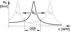
Fig. 2. Mechanical
system’s tuning principle
In our laboratory, in order to carry out our
complex research practice, we need torsional oscillation exciters, which
operate on various principles, in addition to torsional oscillation tuners. The
objective of this paper is to perform a harmonic analysis of a special
torsional oscillation force excitation mechanism, in order to identify the
possibilities of its application.
2. force
torsional oscillation excitation mechanism
The
mechanism for force torsional oscillation excitation, as shown in Figure 3,
produces, during its operation, the load torque of an alternating character.
The force of the extended tension spring (1) and arm depends on the turn angle
of the rotary flange, on which the excentre is (4) mounted. To avoid damage to
the spring eyes during operation of the mechanism (as a consequence of
frictional wear), it is necessary to use bearings in places (2) and (3). It is
possible to adjust the spring preload by a spring extension fixed to the base
plate (5). As we can see in Figure 3b, this mechanism can be mounted:
·
to
the frontal surface of the driving or driven machine flange
·
to
the crank of the crankshaft situated in the drive chain of a mechanical system
|
|
|
|
a) |
b) |
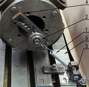
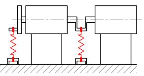
Fig. 3. Force torsional oscillation
excitation mechanism: a) construction example and b) application
scheme
3. Derivation
of mathematic formulas for force excitation
In Figure 4, a schematic drawing of
the given mechanism with force terms is presented.
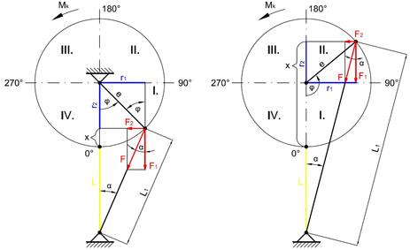
Fig. 4. Mechanism scheme
with force terms
Consequently, as shown in Table 1,
formulas are derived for torque Mk
from Figure 4, where: Mk - torque,
which it is necessary to expend on rotation in the direction of rotation angle φ, which increases
counterclockwise; F - spring force, which is
decomposed to components F1
and F2; L - distance of the axes of the
spring grip pins in the bottom dead centre.
Tab. 1
Derived formulas for torque Mk
|
All
quadrants |
Quadrant
III |
Quadrant
II |
|
|
|
|
|
Quadrant
IV |
Quadrant
I |
|
|
|
|


4. HARMONIC
ANALYSIS OF the EXCITATION
In Table 2, the amplitude values of
the first, second and third harmonic components (HCs) and the various
eccentricity values of the phase angle without a spring preload are computed.
The amplitudes of higher HCs have only a negligible size (less than 1% of the
first HC amplitude).
Tab. 2
Computed values of harmonic components without
spring preload
|
Eccentricity [% of L] |
1st HC amplitude MA1 [N.m] |
(MA2/MA1).100 [%] |
(MA3/MA1).100 [%] |
2nd HC phase
angle shifting ψ2
[°] |
3rd HC phase
angle shifting ψ3
[°] |
L [m] |
|
1 |
0.040.x |
49.443 |
0.367 |
180.5 |
181 |
Constant |
|
5 |
x |
47.324 |
1.700 |
180.5 |
181 |
Constant |
|
10 |
4.019.x |
44.896 |
3.060 |
181 |
Constant |
|
|
15 |
9.076.x |
42.686 |
4.171 |
180.5 |
181 |
Constant |
|
20 |
16.187.x |
40.668 |
5.075 |
180.5 |
181 |
Constant |
|
25 |
23.359.x |
38.817 |
5.808 |
180.5 |
181 |
Constant |
|
50 |
102.238.x |
31.503 |
7.818 |
180.5 |
181 |
Constant |
In Table 3, the amplitude values of
the first, second and third harmonic component (HCs) involving various spring
preloads with a constant eccentricity value of 10% of L are computed. The value of ψ2,
in all cases, is 180.5°, while the value of ψ3,
in all cases, is 181°.
Tab. 3
Computed values of harmonic components with spring
preload
|
Eccentricity [% of L] |
1st HC amplitude MA1 [N.m] |
(MA2/MA1).100 [%] |
(MA3/MA1).100 [%] |
Spring preload [stretched % of L] |
L [m] |
|
10 |
x |
44.896 |
3.060 |
0 |
Constant |
|
10 |
1.494.x |
28.541 |
1.945 |
5 |
Constant |
|
10 |
1.990.x |
20.318 |
1.385 |
10 |
Constant |
|
10 |
2.483.x |
15.369 |
1.047 |
15 |
Constant |
|
10 |
2.977.x |
12.063 |
0.822 |
20 |
Constant |
|
10 |
3.472.x |
9.699 |
0.661 |
25 |
Constant |
|
10 |
3.966.x |
7.924 |
0.540 |
30 |
Constant |
|
10 |
4.461.x |
6.542 |
0.446 |
35 |
Constant |
|
10 |
4.955.x |
5.437 |
0.370 |
40 |
Constant |
It
is possible to describe the dependence of load torque Mk, which arises during the operation of the given
mechanism, on rotation angle φ
using the following formula:
Mk = MA1.sin φ + MA2 sin (2.φ + ψ2) + MA3 sin (3.φ + ψ3),
where:
MA1, MA2, MA3
- amplitudes of the first, second and third HCs of excitation; Ψ2 and Ψ3 - phase angle
shifting of these second and third HCs towards the first HC.
5. CONCLUSION
From the
values stated in Tables 2 and 3, it is possible to say that:
·
Without a spring preload, but with a linearly
increasing eccentricity percentage value, the first HC amplitude value
increases quadratically, the second HC amplitude percentage decreases and the third HC percentage
increases.
·
With a suitable spring preload, we can increase the
first HC amplitude value, substantially reduce the second HC amplitude value and minimize the
third HC amplitude value to a negligible size (less than 1% of the first HC
amplitude).
These
facts relate to the property of the given mechanism (not its deficiency). Among
general advantages of the mechanism, it is possible to mention:
·
Negligible small friction resistances while
operational
·
Simplicity of its construction and therefore low
manufacturing costs
·
Simple and accurate calculation of load torque
dependence
The main
disadvantage of the given mechanism is the rise of relatively high radial
loading in the system at the point of the excentre in relation to the rotary
part mounting, which should be provided at the shafts, and the dimension of the
bearings.
References
1.
Czech P., J. Mikulski. 2014.
“Application of Bayes Classifier and Entropy of Vibration Signals to Diagnose
Damage of Head Gasket in Internal Combustion Engine of a Car”. In: J. Mikulski
(ed.). 14th International Conference on Transport Systems Telematics. Katowice
Ustron, Poland. 22-25 October 2014. Telematics - Support for Transport. Book
series: Communications in Computer and Information Science, Vol. 471: 225-232.
2.
Czech
P. 2013. “Intelligent approach to valve clearance diagnostic in cars”. In:
J. Mikulski (ed.). 13th International Conference on Transport Systems
Telematics. Katowice Ustron, Poland. 23-26 October 2013. Activities of
Transport Telematics. Book series: Communications in Computer and Information
Science, Vol. 395: 384-391.
3.
Figlus Tomasz, Marcin Stańczyk.
2016. “A method for detecting damage to rolling bearings in toothed gears of
processing lines”. Metalurgija 55(1): 75-78. ISSN: 0543-5846.
4.
Figlus Tomasz, Marcin Stańczyk.
2014. “Diagnosis of the wear of gears in the gearbox using the wavelet packet
transform”. Metalurgija 53(4): 673-676. ISSN: 0543-5846.
5.
Folega
Piotr, Grzegorz Wojnar, Rafał Burdzik, Łukasz Konieczny. 2014. “Dynamic
model of a harmonic drive in a toothed gear transmission system”. Journal of Vibroengineering 16 (6):
3096-3104. ISSN 1392-8716.
6.
Fraunhofer L.B.F. 2015. Gesteigerter Yacht-Genuss: Aktive Kupplung
mindert Schwingungen in Schiffsantrieben. [In German: Increased Yacht Enjoyment: Active Clutch
Reduces Vibration in Ship Propulsion Systems.] Available at:
http://www.lbf.fraunhofer.de.
7.
Gąska Damian, Tomasz Haniszewski,
Jerzy Margielewicz. 2017. “I-beam girders dimensioning with numerical modelling
of local stresses in wheel-supporting flanges”. Mechanika 23(3): 347-352. ISSN
1392-1207.
8.
Homišin Jaroslav. 2002. Nové typy pružných hriadeľových spojok:
Vývoj-Výskum-Aplikácia. [In Slovak: New
Types of Flexible Shaft Couplings: Development-Research-Application.]
Košice: Vienala. ISBN 80-7099-834-2.
9.
Homišin Jaroslav. 2006. “Tuning methods of mechanical systems
by means of torsional oscillation tuner application”. Pneumatyka 61 (6): 32-35. ISSN 1426-6644.
10.
Homišin Jaroslav, Peter Kaššay.
2014. “Experimental
verification of the possibility using pneumatic flexible shaft couplings for
the extremal control of torsional oscillating mechanical system”. Diagnostyka 15 (2): 7-12. ISSN
1641-6414.
11.
Kaššay Peter. 2017. Pneumatická pružná hriadeľová spojka s
hadicovým pružným elementom. [In Slovak: Pneumatic Flexible Shaft Coupling with Hose-resilient Element.]
Utility pattern SK 7708 Y1. Banská Bystrica: ÚPV SR 2017.
12.
Lacko Pavol. 1988. “Die kontinuierliche Änderung
dynamischer Parameter von Schwingungssystemen im Betriebszustand”. [In German:
“The continuous change of dynamic parameters of vibration systems in the
operating state.”] Maschinenbautechnik
6: 274-277.
13.
Mario De Luca. 2017. ”A comparison
between prediction power of artificial neural networks and multivariate
analysis in road safety management”. Transport
32(4): 379-385. ISSN: 1648-4142. DOI:
https://doi.org/10.3846/16484142.2014.995702.
14.
Patent
PL 216901 B1. Układ mechaniczny strojony
w sposób płynny. [In Polish: Mechanical
System Tuned in a Smooth Way.] Homišin J., 2014.
15.
Sapieta
M., A. Sapietová, V. Dekýš. 2017. “Comparison of the thermoelastic
phenomenon expressions in stainless steels during cyclic loading”. Metalurgija 56 (1-2): 203-206. ISSN
0543-5846.
16.
Wittek
Adam Marek, Damian Gąska, Bogusław Łazarz, Tomasz Matyja. 2014. “Automotive stabilizer bar – stabilizer bar strength calculations
using FEM, ovalization of radial areas of tubular stabilizer bars”. Mechanika
20(6): 535-542. ISSN 1392-1207.
This paper was written within the
framework of the KEGA 041TUKE-4/2017 grant project entitled, Implementation of
New Technologies Specified for Solving Questions Concerning the Emissions of
Vehicles and Their Transformation in Educational Processes in Order to Improve
the Quality of Education.
This article was created with
support from the PhD students and young researchers project entitled, Solution
of a Control System Element for Mechanical Systems’ Continuous Tuning.
Received 19.08.2017; accepted in revised form 01.11.2017
![]()
Scientific Journal of Silesian
University of Technology. Series Transport is licensed under a Creative
Commons Attribution 4.0 International License