Article citation information:
Warczek, J. A study on exposing the driver of a commercial vehicle to
mechanical vibration. Scientific Journal
of Silesian University of Technology. Series Transport. 2017, 94,
229-238. ISSN: 0209-3324. DOI: https://doi.org/10.20858/sjsutst.2017.94.20.
Jan
WARCZEK[1]
A study oN exposing the driver of a commercial vehicle
to mechanical vibration
Summary.
This article presents the results of research whose objective was to assess the
risks of vibration in the workplace to a driver of a commercial vehicle. Under
current EU law on working time, daily vibration exposure for drivers of
commercial vehicles should be determined for every nine hours of work. Research
on nuisance vibrations on a driver was carried out on a commercial vehicle
operated under normal conditions in urban traffic and outside urban areas.
Vibration exposure assessment was separately made for each direction of
vibration influence. The obtained results enable us to conclude that drivers of
commercial vehicles are exposed to harmful vibrations, which largely exceed the
limits of exposure to mechanical vibrations in general.
Keywords: exposure to vibration, commercial vehicle, work
safety
An important factor that impacts on
traffic safety is the psychomotor performance of the driver. Any decrease may
result from the harmful effects of vibration, to which the driver is exposed
during transport tasks. The degree of the impact of vibration is dependent on
many factors. The most important of which include the extortion and propagation
of vibration in the mechanical structure of the vehicle [6]. The basic elements
of the mechanical structure of the car responsible for minimizing vibrations
are cushioning units, such the suspension system for the wheels, pneumatic
tyres, suspension systems of the engine, the transmission system, and the
suspension of the driver�s cab with a seat suspension system. The greatest
energy resulting from mechanical vibrations takes over the suspension of the
vehicle, along with the chassis. The system consists of elements connecting the
wheels to the frame of a commercial vehicle [1], which adapt to all the loads
acting on the wheels. A typical solution for the chassis and suspension
consists of:
�
axis
of the wheels (rigid beam axle wheel or driving axle housing)
�
bearing
units of the wheels
�
road
wheels (rigid metal rims with pneumatic tyres)
�
elastic
elements (steel or pneumatic spring)
�
vibration
dampers (viscous dampers and vibration-isolating elements based on elastomers)
�
guide
elements in the suspension system (control arms, radius rods)
The purpose of the suspension system
and pneumatic wheels is the amortization of the body, or the mitigation of
vibrations that are caused, for example, by driving on bumpy roads. On the
other hand, the elastic fastening of the wheels to the body results in the
potential for resonant vibrations, which adversely affect the ability to
transfer forces from the dynamic system of the vehicle to the road surface.
Excessive vibrations of the wheels also cause considerable dynamic loads of the
tyres and the road surface. This is why the suspension system involves the
efficient use of vibration dampers in the form of hydraulic shock absorbers [7,
8].
By damping and mitigating the
dynamic interactions between the uneven road surface and the wheels of the car,
the suspension system ensures a comfortable ride at an appropriate level,
together with the protection for passengers and cargo, while maintaining
security due to the adhesion of wheels to the surface [5, 11]. The issues are
particularly important when driving at the high speeds that modern commercial
vehicles can reach.
2. RESEARCH PROBLEM
The cabin, which is a separate part
of the body of the truck, is the workplace of the driver. In modern commercial
vehicles, it is elastically mounted to the frame by elastic means (steel or
pneumatic springs) and damping elements (hyperviscous dampers). In addition,
the cabin is protected against high-frequency vibrations using metal-rubber
connectors. Flexible cab suspension meets the need of isolation from the
vibration of the vehicle frame, due to the transfer of vibration from the
wheels and the powertrain. Inside the cabin are seats for the driver and
passengers, as well as devices used to control the vehicle and parameters of
the vehicle systems.
The driver�s seat is usually placed
on seat tracks attached to the cab floor, so that it can be set relative to the
cockpit in order to adapt to the anthropometric measurements of the driver.
Suspension of the modern driver�s seat is based on regulated elastic and
damping elements. Armchairs in modern trucks are equipped with pneumatic
suspension. By changing the air pressure in air cushions, it is also possible
to adjust the vertical position of the seat [1, 2]. Air cushions, placed in the
headrest, allow for a proper fit of its shape to the silhouette of the driver.
Accordingly, the assumed
distribution of vibration is as follows:
�
locally,
it is propagated into the body through the hands
�
generally,
it penetrates the body through the pelvis, legs and back
Drivers of commercial vehicles are
mainly exposed to whole-body vibration due to the work done in a sitting
position. The vibration energy of seats is transmitted to the human body by the
back, pelvis and sides. The negative effects of vibration of a general nature
mainly concern the human skeleton and internal organs. The skeletal lesions
occur primarily in the lumbar spine. Adverse changes in the internal organs, as
a consequence of the impact of overall vibration, are mainly the result of the
stimulation of individual organs by the resonant vibration [7, 9]. This can
lead to the appearance of disturbances in the activities of these organs and,
in extreme cases, mechanical damage to these organs. Even when low energies of
vibration intrude the human body after long exposure times, there are negative
effects of their influence in the form of psychosomatic reactions (fatigue,
elongation of reaction time etc.).
Acceptable exposure to vibration for
drivers of commercial vehicles is determined by the legal acts that define the
daily exposure to vibration. The determination of daily vibration exposure for
professional drivers in the conducted research has been divided into stages:
�
identification
of the series of separate operations performed by the driver during the working
day
�
indication
of the operations to be assessed
�
determination
of the values of effective vibration acceleration (RMS) for each operation
�
determination
of the average daily exposure times for each operation
�
calculation
of the daily exposure to vibration
According to the current European
Parliament and Council Regulation No. 561/2006 of 15 March 2006, the daily
driving time, which is understood as the total driving time between the end of
one daily rest period and the beginning of the following daily rest period, or
between a daily rest period and a weekly rest period, shall not exceed nine
hours and can be twice-weekly extended to 10 hours [10]. In planning the
driving time, 45 minutes should be allocated for breaks. It must therefore be
assumed that the daily vibration exposure for drivers of commercial vehicles,
subject to working time registration, should be determined for at least nine
hours of work.�
Research on the vibration nuisance
regarding the driving position was carried out on the MAN TGL 12.240, which is
a two-axle commercial vehicle with a box-shaped construction with a permissible
total weight of 12,000 Mg [2]. The scheme adopted in the research regarding
directions of the measurements of vibration acceleration is shown in Figure 1.
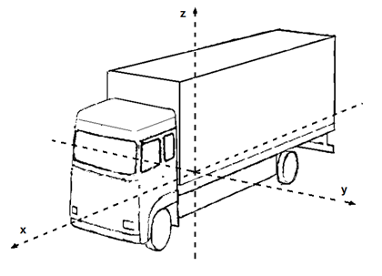
Fig. 1. Directions of vibration measurements in the tested vehicle
The suspension system of the tested
vehicle comprised parabolic springs and a stabilizer on the front axle, and air
springs and a stabilizer on the rear axle. The car was equipped with a low,
elongated cabin, which used four-point suspension. The cabin was amortized from
the frame in the front section by means of mechanical springs, with gas ones in
the rear. They subsequently entered the hydraulic shock absorbers via all four
points of support.
The driver�s seat in the test
vehicle was equipped with a pneumatic suspension, which facilitated
longitudinal adjustment of the seat height and adjustment of the seat tilt. The
seat also provided a rest position and the rapid lowering of the seat for easy
entry and exit from the car. Views of the driver�s seat in the cabin and the
method of affixing of measuring pads using acceleration sensors are shown in
Figure 2.
During the measurements, the driver
was subjected to vibrations, whose main source was uneven surface and changing
traffic conditions resulting from changes in the volume of traffic on the whole
route. The measurements were carried out while driving without a load. The test
vehicle moved along roads located in urban areas and on rural roads. Vibration
tests were also conducted on the seat while moving on the highway. The route
was chosen in such a way as to best reflect the working conditions of the
driver during a typical day of work, that is, in changing traffic, which is
associated with the distance from the city centre, and variable surface
conditions resulting from the road class.
The measuring set used in the study
consisted of a triaxial acceleration converter mounted on a rubber vibration
pad (Fig. 2b), which cooperated with the data acquisition and analysis module.
The converter was set up in such a way that the x direction coincided with the
direction of straight-ahead driving.
|
a) |
���������� b) |
|
|
|
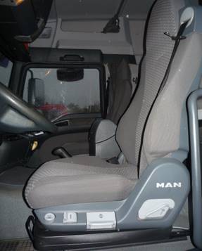
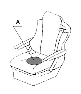
Fig. 2. View of the driver�s seat in
the MAN TGL: (a) the scheme of placing the vibration acceleration sensor on the
seat and (b) the rubber cushion (A) of the vibration acceleration sensor
During the study, effective values
of vibration acceleration a(t) were recorded in three directions consistent
with Figure 1. Effective values characterizing the energy impact of vibration
on the driver were determined according to Formula 1.
![]() �����������������������������������������������������(1)
�����������������������������������������������������(1)
where
T represents the time of measurement and a(t) represents the instantaneous
values of vibration acceleration.
The recorded vibration signals
indicate a stationary character on the roads with a good surface and a pulsed
(non-stationary) character on suburban roads in a poor state with many ruts and
flumes. The measured values of vibration acceleration were also influenced by
driving style (traffic flow), which changed during the experimental passage.
4. RESULTS AND ANALYSIS
Measurements of RMS vibration
acceleration were made in three directions: x, y, z. The measurements were
carried out in a cyclic mode, yielding a series of effective value vibration
acceleration in a given direction of measurement. The results were divided by
the types of road on which the vehicle moved according to the adopted
classification for roads: urban, extra-urban and motorway. To assess the
harmfulness of vibrations to humans, we used the vibration energy measure,
marked out for an appropriately selected frequency band. The effective value of
vibration acceleration awRMS for each direction of measurement (x,
y, z) for a cycle involving an 1 h ride was determined as:
![]() ���������������������������������������������������(2)
���������������������������������������������������(2)
where
T represents the reference time of 1 hour and aj represents the instantaneous values of vibration acceleration recorded
at time tj.
Substitute values of vibration
acceleration asub,i have been designated as the sum of the vector
acceleration operating in three orthogonal directions (Equation 3). This is a measure
of the impact of vibrations mainly used in local vibration analysis. In the
case of drivers of motor vehicles, the presence of seat vibration is associated
with the relative movements of the seat and cabin floor together with the
cockpit. The relative movements of the driver on the seat give the effect of
local vibrations penetrating the body through the hands, which rest on the
steering wheel.
![]() �����������������������������������������(3)
�����������������������������������������(3)
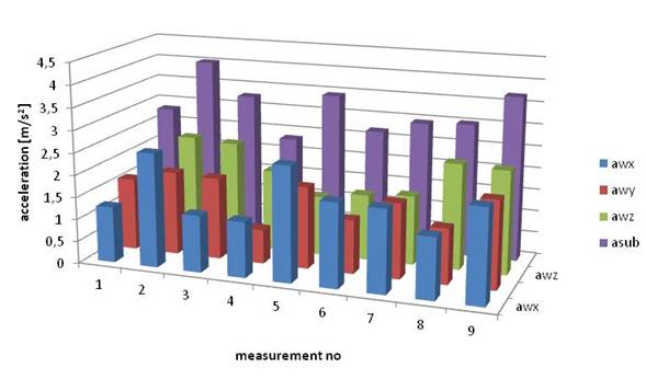
The results of effective value
measurements (aRMS) of vibration acceleration for various directions
of measurement, as well as the resultant acceleration, are shown in Figures
3-5. The numbers of measurements represent the consecutive hours of
observation.
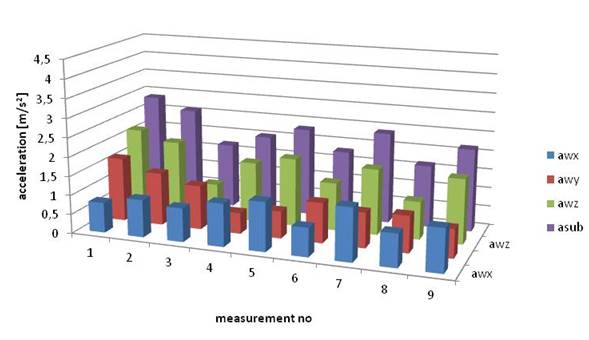 �Fig. 3. The results obtained for roads in urban areas
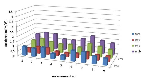
 �Fig. 4. The results for roads in
extra-urban areas
�Fig. 4. The results for roads in
extra-urban areas
 �Fig. 5. The results for highways
The daily vibration
exposure in each direction of the measurement of vibration acceleration for
different types of road was calculated according to Formula 4, which
incorporates a nine-hour working time limit for drivers:
![]() ���������������������������������������(4)
���������������������������������������(4)
where awRMS(x,y,z) represents the
effective value of vibration acceleration for a specific
operation in the direction x, y or z (m/s2); n
represents the number of
occasions involving 1 h measurements (n = 9); i represents the numbers of successive 1 hr vibration observations; ti
represents the duration of the operation equal to
3,600 (s); T0 represents
the reference time equal to 32,400 (s); and k(x,y,z)
represents the value of the weighting
factor. For the directions x, y, k = 1.4; for the direction z, k = 1.
A summary of the
research results concerning the driver of a commercial vehicle�s exposure to
vibrations while driving on various road surfaces is shown in Figure 6.
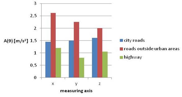 �Fig. 6. The value of the driver�s exposure to vibrations (for nine hours) when
driving on roads of different categories
�Fig. 6. The value of the driver�s exposure to vibrations (for nine hours) when
driving on roads of different categories
Vibration
exposure assessment was separately conducted for each direction of vibration
influence. In the case of movement on roads located in urban areas, the highest
values occurred in the vertical direction. In non-urban traffic, the maximum
values of exposure occurred in the longitudinal direction. Similarly, in
motorway traffic, the highest value of exposure occurred in the direction of
the longitudinal axis of the vehicle. For all tested directions, the effects of
vibration energy on the vehicle driver while driving on the selected road types
were the selected maximum values; this is consistent with the assessment
procedure specified in the standard [3].
5.� SUMMARY
For a driver of a commercial
vehicle, who is used to roads of different categories, the daily exposure level
depends largely on the condition of the road surface. The test vehicle was in
good condition, which was confirmed before and after the conducted research by
service inspections. It transpires that, during transportation tasks, in the
shuttle cycle, when using roads outside urban areas, the exposure limits for
vibration are likely to be substantially exceeded. This is particularly
important when planning driving routes, where route selection may result in a
negative impact on the vehicle driver. Limit values for exposure to general
vibrations in an eight-hour working cycle are set out in the Annex to the
Regulation of the Minister of Labour and Social Policy of 29 November 2002
[4]. According to this document, vibrations that have a general impact on the
body should not exceed the value of daily exposure A(8) for 0.8 m/s2.
Summing up the results of this
research, it is clear that drivers of commercial vehicles are exposed to
harmful vibrations, which significantly exceed the limits of exposure to
general mechanical vibrations. There is also an incompatibility between the
regulation of drivers� working time and the standards related to daily exposure
to vibrations. It is therefore important to continue working on design
solutions that can reduce the value of drivers� exposure to mechanical
vibrations, as well as synchronize the legal frameworks for the regulation of
drivers� working time and daily vibration exposure.
References
1.
Prochowski
Leon, �uchowski Andrzej. 2016. Trucks and
buses. Warsaw: WKi�. ISBN
9788320619706.
2.
MAN TGL 12.240 User Manual.
3.
PN-EN
14253+A1: Drgania mechaniczne. Pomiar i obliczanie zawodowej ekspozycji na
drgania o og�lnym dzia�aniu na organizm cz�owieka dla potrzeb ochrony zdrowia.
Wytyczne praktyczne. Stycze� 2011. [In Polish: PN-EN 14253+A1: Mechanical
vibration. Measurement and calculation of occupational exposure to vibrations
of the general impact on the human body for health. Practical guidance.
January 2011].
4.
Rozporz�dzenia
Ministra Pracy i Polityki Spo�ecznej z dnia 29 listopada 2002 r. w sprawie
najwy�szych dopuszczalnych st�e� i nat�e� czynnik�w szkodliwych dla zdrowia w
�rodowisku pracy (Dz. U. z 2002 r. Nr 217 poz. 1833; Dz. U. z 2005 r. Nr 212
poz. 1769; Dz. U. z 2007 r. Nr 161 poz. 1142; Dz. U. z 2009 Nr 105 poz. 873;
Dz. U. z 2010 Nr 141 poz. 950). [In Polish: Regulation of the Minister of
Labour and Social Policy of 29 November 2002 on the maximum permissible
concentration and intensity of harmful factors in the work environment (Dz. U.
z 2002 r. Nr 217 poz. 1833; Dz. U. z 2005 r. Nr 212 poz. 1769; Dz. U. z 2007 r.
Nr 161 poz. 1142; Dz. U. z 2009 Nr 105 poz. 873; Dz. U. z 2010 Nr 141 poz.
950)].
5.
Warczek
Jan, Rafa� Burdzik, �ukasz Konieczny. 2016. �Analysis of the forces generated
in the shock absorber for conditions similar to the excitation caused by road
roughness. Dynamical systems: theoretical and experimental analysis�. ��d�,
Poland, December 7-10, 2015. In Jan Awrejcewicz (ed.), Springer Proceedings in Mathematics & Statistics, Vol. 182, P.
373-383. Berlin: Springer International Publishing.
6.
Burdzik
Rafa�, Aleksander Lisiecki, Jan Warczek, �ukasz Konieczny, Piotr Fol�ga,
Agnieszka Szkliniarz, Grzegorz Siwiec. 2016. �Research on vibration properties
of copper-titanium alloys.� Archives of
Metallurgy & Materials, Vol. 61, Iss. 1: 315-322. ISSN 1733-3490.
7.
Warczek
Jan, Jakub M�y�czak, Rafa� Burdzik, �ukasz Konieczny. 2015. �Simulation of a
visco-elastic damper based on the model of the vehicle shock absorber�. Journal of Vibroengineering, Vol. 17,
No. 4: 2040-2048. ISSN 1392-8716.
8.
Warczek
Jan. 2014. �The diagnostic model of a nonlinear viscoelastomeric damper�. Diagnostyka, Vol. 15, No. 4l: 29-34.
ISSN 1641-6414.
9.
Kozuba
Jaros�aw, Pila Jan. 2015. �Selected elements influencing pilot situational
awareness�. Advances in Military
Technology, Vol. 10(2): 45-55. ISSN 18022308.
10.
Regulation
(EC) No. 561/2006 of the European Parliament and of the Council of 15 March
2006 on the harmonization of certain social legislation relating to road
transport and amending Council Regulations (EEC) No. 3821/85 and (EC) No.
2135/98 and repealing Council Regulation (EEC) No. 3820/85 (Text with EEA
relevance): Declaration.
11.
Konieczny �ukasz, Rafa� Burdzik, Jan Warczek, Piotr
Czech, Grzegorz Wojnar, Jakub M�y�czak. 2015. �Determination of the effect
of tire stiffness on wheel accelerations by the forced vibration test method�. Journal of Vibroengineering, Vol. 17,
Issue 8: 4469-4477. ISSN 1392-8716.
Received 27.11.2016;
accepted in revised form 15.01.2017
![]()
Scientific Journal of Silesian University of
Technology. Series Transport is licensed under a Creative Commons
Attribution 4.0 International License