Article citation information:
Piľa, J., Korba, P., Hovanec, M. Aircraft brake temperature from a
safety point of view. Scientific Journal
of Silesian University of Technology. Series Transport. 2017, 94,
175-186. ISSN: 0209-3324. DOI: https://doi.org/10.20858/sjsutst.2017.94.16.
Ján PIĽA[1], Peter KORBA[2],
Michal HOVANEC[3]
AIRCRAFT BRAKE TEMPERATURE FROM A SAFETY POINT OF VIEW
Summary. Safety is critical throughout all stages of
aircraft operation, from air mission to ground operation. One of the most important
airframe systems that influences the efficacy of ground safety is a wheel brake
system. Aircraft ground speed deceleration requires the dissipation of kinetic
energy, which depends on aircraft weight and speed. Significant levels of
aircraft kinetic energy must be dissipated in the form of heat energy. The
brakes of heavy aircraft are especially prone to overheating during landing and
taxiing on the ground. The aim of this paper is to focus on the dangers caused
by aircraft brakes when overheating and ways in which to eliminate brake
overheating problems from a safety perspective.
Keywords: brake, temperature, overheating, aircraft safety,
brake cooling
1.
INTRODUCTION
Wheels, tyres and brakes are critical to ensure safe and reliable
aircraft ground operation. The primary purpose of aircraft wheel brakes is to
decelerate and stop an aircraft by transforming the kinetic energy into heat
energy via friction and dissipation of heat to the surroundings.
The secondary function of aircraft wheel brakes is to hold the aircraft
stationary during the engine’s run-up and, in many cases, steer the aircraft
during taxi.
Aircraft brakes are arranged in multiple disk pairs, which are commonly
referred to as the brake heat sink. Two main methods of increasing aircraft
friction or drag are applied:
•
air friction: aerodynamic drag
(airbrakes, spoilers, flaps, reverse thrusters, drag shuts etc.)
•
ground friction: wheel brakes
(aircraft to ground drag)
The weight and speed of an aircraft during landing and taxing determine
how much energy the brake friction material absorbs.
Brake sizing is based on heating during a single landing and takes into
account that ventilation has a limited effect, while neglecting the
contribution of possible thrust reversal, flaps and spoilers. This means that a
high part of the kinetic energy on landing will be converted into brake
heating; the part of the brakes that is involved is often referred to as the
heat sink. This event can be expressed by a simple formula of energy balance
[1, 2]:
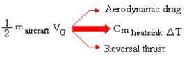
where
m refers to mass, VG refers to ground speed, C refers to a specific
head of heat sink material and T refers to temperature.
Wide body and military aircraft brakes use multidisc of rotor and stator
brakes (Fig. 1). Brake housings contain several pistons for applications of the
normal force needed to develop the brake torque.
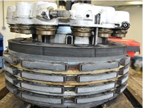
Fig. 1. Multidisc brake
Source: authors’ ABT Košice wheel and brake shop
The landing kinetic energy of modern aircraft equates to several million
joules. The brakes of large commercial aircraft must be capable of absorbing up
to 135 MJ of energy. This enormous energy, when absorbed by the brakes within
10-12 s after landing, imposes severe thermal gradients of thousands of degrees
centigrade per cm2 across the friction elements and brake bulk
temperatures of 1,000°C or more [3].
Brake materials have additional requirements, such as resistance to
corrosion, light weight, long life, low noise, stable friction, low wear rate, and
acceptable cost versus performance. The design of the brakes affects heat flow,
reliability, noise characteristics and ease of maintenance.
This energy conversion process produces very high energy fluxes at the
multiple friction interfaces, resulting in high temperatures and stresses in
the brake heat sink. The friction and wear characteristics of the friction
materials used in aircraft brakes are influenced by internal factors (such as
friction-material composition and heat sink mass) and external factors (such as
the amount of kinetic energy absorbed by the brake, the surface velocity of the
friction interfaces and aircraft deceleration requirements). Simply put, these
factors control the temperature at the interface as well as the normal and
tangential forces of the friction material.
Potential problems related to excessive brake energy are:
•
brake overheating
•
brake fire
•
brake fade
•
brake welding
•
failure of brakes or associated
components
•
fuse plug melt
2.
OVERHEATING OF BRAKES
During normal or emergency aircraft braking, the landing gear of the
aircraft is highly stressed and therefore deserves special attention. Due to
increased weight (Airbus A380 MTOW = 575 tonnes) and higher landing speed
(Airbus A380 = 240-250 km/h) of modern aircraft, as well as the requirement of
extreme braking for the shortest path (for the Airbus A380, it is 2000 ft =
609.6 m of runway), brakes overheating are a frequent phenomenon. It is
therefore understandable that the overheating of the brakes constitutes a
hazard. Overheated wheels and tyres pose a risk of possible explosion because
tyre pressure will increase considerably.
When parking the aircraft, it is therefore recommended to cool
overheated wheel brakes and tyres, as well as provide aircraft parking in
isolated areas. Using water as the cooling medium is not recommended unless it
is necessary to protect people in the vicinity of overheated wheels.
The ICAO recommendation is thus: too rapid cooling of a hot wheel,
especially if localized, may cause explosive failure of the wheel. Water fog
can be used, but intermittent application of short bursts of 5-10 s every 30 s
is recommended. Dry chemicals have
limited cooling capacity but are an effective extinguishing agent. Once the
tyres are deflated, any extinguishing agent may be safely used as there is no
further danger of explosion.
Thermal fuse plugs (Fig. 2) prevent the violent explosion of tyres when
maximum temperatures are exceeded. Most wheels of jet aircraft have fusible
plugs, which melt at specified temperatures (e.g., 177°C) and deflect the tyre
before dangerous pressures are reached.
The maximum temperature of the wheel may not be achieved in the period
up to 15 to 20 min when the aircraft exits the process of landing and taxiing.
Most modern large aircraft have temperature sensors built into the landing
gear.
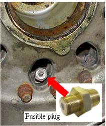
Fig. 2. Fusible plug on the wheel disc
Source: http://www.airliners.net/forum/viewtopic.php?t=594267
Taxing over a longer period at a higher speed may increase brake temperatures
and cause subsequent fire in the wheel well at the stage of take-off for the
aircraft. In this case, a flight with landing gear extended for a period of
several seconds allows for rapid cooling of the brakes. Further, a flight with
extended landing gear may continue until the warning light “OWH” turns off.
Boeing 747 has prescribed a speed limit during taxiing (maximum 10
km/h-1) before stopping, followed by
landing gear checking and brake cooling.
During aircraft landing with intensive braking, in order to reduce
landing run distance, certain types of anti-skid devices are damaged by
overheating conditions.
The landing weight and interval before take-off play an important role
in respect of the brake temperature, which has to be very carefully monitored
in order to avoid exceeding the limit needed for energy stopping distance. Hot
brakes can severely decrease braking performance in the event of a rejected
take-off as well.
3. STRESS-STRAINS ANALYSIS OF BRAKE PLATES USING FINITE ELEMENT ANALYSIS
The aim of the numerical calculation was to compare two variants of
brake pressure plates from the Airbus A320. Stress-strain analysis was focused
on the identification of the most exposed areas, which could be the most
probable areas of crack initialization (Fig. 3).

Fig. 3. Crack in the brake pressure plate
Source: author’s ABT Košice wheel and brake shop
For this purpose, a nonlinear analysis was performed using the NX
Nastran program, in which a simulated load was applied to the pressure plate’s
plastic deformation (Fig. 5). For the purpose of comparison, the load applied
to both plates was identical.
Load conditions were established on the basis of input data and the
formation of plate loading during braking.
Input data were received by the company that performed the analysis:
•
material: steel size 17
•
density: 7,928 kg/m3
•
modulus: E = 19,3140 MPa
•
Poisson’s ratio: μ = 0.3
•
yield strength: Re = 280 MPa
•
tensile strength: Rm = 520 MPa
•
specific rate capacity: Cp = 0.49 kJ/kg°C
•
pulse expansion: α = 13.10-6 m/mK
•
coefficient of friction: f = 0.57
• contact force: Fn = 285 kN
Figure 4 depicts the course of the brake temperature increase and the
brake temperature decrease (cooling).
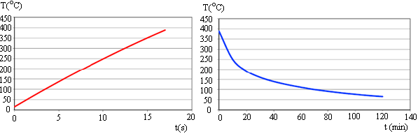
Fig. 4. Brake temperature increase and decrease
Source: authors
According to the analysis (based on
a comparison of both models), it is evident that, under the same load
conditions, there are more striking plastic deformations on Plate 1 than on
Plate 2. A higher degree of plastic deformation of Plate 1 is linked to a
higher probability of material deterioration under cyclic stress-strain
conditions. Areas of material deterioration are mainly located at the end of
dilatation slots, which are missing from Plate 2 (Fig. 5). From this point of
view, the pressure from Plate 2 leads to better stress distribution around the potential stress concentrators (Fig. 5).
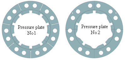
Fig. 5. Pressure plates from multidisc brakes
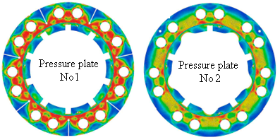
Fig. 6. Heat stress fields of pressure plates
Source: authors
4. BRAKE FIRE, FADE AND WELDING
When hydraulic fluid leaks onto the
hot brake components, the fluid causes fire to break out. A mixture of the two
types of hydraulic fluid lowers the temperature at which the fluid ignites,
that is, below the flashpoint of pure MIL-H-83282 fluid.
An aircraft maintenance mechanic
indicated that the two mixed hydraulic fluids, which are compatible, will
reduce the fire resistance of the fluid.
Exxon HyJet IV-Aplus fire-resistant
aviation hydraulic fluid has the following flammability:
·
flash point =
174ºC
·
fire point =
185ºC
·
auto-ignition
point = 427ºC
Another reason for a fire caused by
overheated brakes is their proximity to the hydraulic and electrical system. In
the case of Nigeria Airways flight 2120: “When the landing gear was retracted…
burning rubber was brought into close proximity with hydraulic and electrical
system components… causing the failure of both hydraulic and pressurization
systems that led to structural damage and loss of control of the aircraft.” The
cause of the crash was found to be under-inflated tyres, which in turn caused
overheated tyres to catch fire and the failure of the hydraulic systems.
Brakes can overheat for many
reasons. A “dragging brake” can heat up on a long taxi and take-off run. When
retracted into the wheel well, this can cause all sorts of problems. Taxiing
too fast over long distances can cause these temperatures to become so hot that
wheel well fires can develop after take-off. On large aircraft, brakes will
reach their hottest point up to 15 min after landing.
Brake fade is a term used to
describe the partial or total loss of braking power used in a vehicle brake
system (Fig. 7). Brake fade occurs when the brake pad and the brake rotor no
longer generate sufficient mutual friction to stop the vehicle at its preferred
rate of deceleration. The brake pad in any brake system is designed to work at
certain operating temperatures.
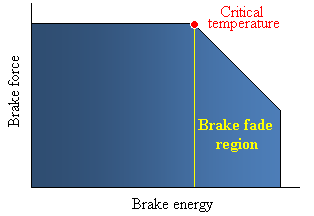
Fig. 7. Brake and brake fade region
Source: authors
New generations of passenger and
freight aircraft are equipped with carbon brakes, as opposed to steel brakes
found on relatively older aircraft. Carbon brakes have different
characteristics and should be operated differently than steel brakes. When
operating an aircraft equipped with steel brakes, the aircraft is required to
use full reverse thrust and minimum braking to minimize the heat input into the
brake assembly (rotors and stators). On long runways, braking can be delayed
until the taxi speed is reached. This is especially convenient when the
aircraft is not on the ground long enough for the brakes to cool. Carbon brakes
have better properties in comparison to steel brakes: they are lighter and can
absorb much more heat during a high-speed rejected take-off, as their stopping
capability improves as they are warmed up [1,
2].
Maximum steel brake life can be
achieved during taxi by using a large number of small and light brake
applications, allowing some time for brake cooling between applications. Carbon
brake wear is primarily dependent on the total number of brake applications:
one firm brake application causes less wear than several light applications [4]. Carbon brakes are not susceptible to “welding”.
5. TEMPERATURE SENSING AND
MONITORING SYSTEM
The heating of aircraft wheels and tyres
presents a potential explosion hazard, greatly increased when fire is present.
Modern
passenger airliners are equipped with “BRAKE HOT” (Airbus) or “BRAKE OVHT” (Boeing)
warnings for individual wheel brakes on the alert displays when the temperature of a brake
rises above a predetermined level and turns off when all the brakes have cooled
to a certain level.
The
reason for the “BRAKE HOT/OVHT” warning is to eliminate the possibility of
flames caused by hydraulic fluid (in the case of a leak of hydraulic fluid)
when the landing gear is retracted into the wheel well. A warning will
automatically start when the temperature reaches 400°C at the hottest part of
the brake lining. The temperature of 400°C ensures the lowest limit of the
auto-ignition of all hydraulic fluids used in the brake system. This mainly
involves liquid Hyjet IV or IV+, whose temperature of auto-ignition (427°C) is
specified under test conditions (under real conditions, the temperature of
auto-ignition is considered to be much higher). The temperature indicated in
the cockpit associated with the “BRAKE HOT” signal depends on the type and
location of the temperature brake sensor. This temperature occurs in between
185°C and 260°C for carbon brakes. If the temperature is above this value, the
alarm “BRAKE HOT” is signalled as “ON”, which means that take-off is not
possible, as this may cause a fire in the landing gear wheel well in the event
of hydraulic fluid leakage. Published ECAM procedures require a delay in
take-off until the alarm goes to “OFF”. The alarm goes out when the temperature
is 10°C below the temperature of triggering a warning, e.g., 290°C.
Brake
temperatures of each wheel are monitored in order to report brake temperature,
warn the crew of brake overheat and indicate any malfunction, such as a
dragging brake. A brake temperature monitoring system:
•
prevents take-off with a hot brake
•
prevent landing gear retraction with a hot brake
•
monitors for residual braking due to a dragging brake
The
“ON” warning appears at 300°C. To achieve an acceptable level of fire safety
during a flight, Airbus uses a number of measures related to the “BRAKE HOT”
signal. Some operators report that their activity is influenced by the time
required for brake cooling, which is associated with signalling (e.g., 300°C).
6. BRAKES COOLING
Military
and commercial aircraft are being designed for short turnaround times and short
landings distances. These aircraft determinations reduce brake cooling times
between usage and short landing distances, often resulting in the increase in
brake applications. Therefore, brakes are sometimes applied while they are
still hot and when the available kinetic energy in the brake is correspondingly
reduced.
There
are two ways of attacking the problem:
•
make a thorough analysis of the expected
operations and design the brake accordingly
•
provide the brake with a cooling device
Analyses
are provided by the brake manufacturer based on the mission profile data
(temperature spectrum for a particular brake).
The role of any cooling medium is cooling, i.e., reducing the
temperature of the object. This is done on the principle of the output of heat
being by conduction, convection and radiation.
The most widely used principle of brake cooling is heat transfer by convection. Heat transfer
by convection involves the movement of groups of molecules within fluids, such
as liquids or gases (cooling medium) from one place to another.
Although water is a very effective coolant, it is technically and
economically feasible in any airport. On the other hand, there are certain problems associated with the very
intensive cooling effect of overheated brake parts, such as heat shock, which
results in changes in the crystal structure of the materials. Moreover, in
brake discs, cracks can result in brake life reduction. Less serious, but still
an existing problem, is the fact that streams of water, if applied to the
wheel, cause a washout of graphite lubricant materials from the wheel bearing. While air, like water, is a commonly used refrigerant, its cooling
effect is significantly lower than that of water. In order to move heat from an air-cooled
object, the air stream flow to the cooled object needs to be of a high speed.
The higher the speed of the airflow acting on the cooled object, the higher the
transport of thermal energy. In many operating manuals for
propeller aircraft, the necessity to maintain the propeller speed to a proper
regime is stated, in order to create cooling airflow to the wheels.
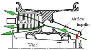
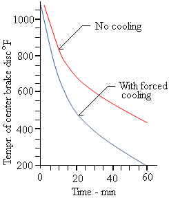
Fig.
9. Forced air brake cooling
Source: Norman S. Currey. 1988. Aircraft Landing Gear Design: Principles
and Practices
Airbus A330 and A380 aircraft can be optionally supplied with integrated
brake cooling fans. These fans are mounted on the brake assemblies of each
brake and thus increase the weight of the aircraft.
Airbus wheel parameters include the following:
·
A380
main wheel tyres that are 1.4 m high and 53 cm wide
·
Maximum
brake temperature for take-off for A320, A330 and A380 is 300°C. This limit
prevents hydraulic fluid leakage, such that any hydraulic fluid that comes into
contact with the brake units will not auto-ignite.
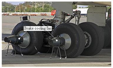
Fig. 8. Forced air brake cooling for
aircraft
Source: http://www.airliners.net/forum/viewtopic.php?t=594267
7.
CONCLUSION
Wheels
and brakes are vital aircraft units, as well as being the most stressed parts
of any aircraft. They are required to safely stop and operate the aircraft on
the ground, often under appalling conditions, during both take-off and landing.
In times of ground operation, they must withstand, absorb and safely dissipate
the tremendous kinetic energy during the slowing-down of an airplane and
bringing it to a safe stop.
Brake
overheating is a potential hazard that can lead to brake fire, brake fade and
brake welding and is considered as a serious problem for modern heavy aircraft,
which is multiplied by short turnaround times and short landings distances for
aircraft. Intensive brake applications, on the one hand, can save fuel and
speed up aircraft turnarounds; on the other hand, the level of safety can be
diminished, while the brake and wheel overhaul may be needed to be more
frequent. From the analysis of the wheel and brake shops, it is clear that the
intensive use of brakes, during aircraft operations, is less concerned with
fuel safety and more about the considerable expense of brake and wheel
overhaul.
For diagnosis purpose, non-invasive methods can be
use. An interesting diagnostic methods are presented by the author in [5-16].
References
1.
Piľa Ján, Kozuba Jarosław, Korba Peter. 2014. Airframe Structure 1. Deblin: Polish Air
Force Academy Publishing.
ISBN 978-83-64636-01-1.
2.
Piľa Ján, Jarosław Kozuba, Grzegorz Peruń. 2014. Aircraft Airframe 1. Gliwice: Silesian
University of Technology Publishing.
ISBN 978-83-7880-230-3.
3.
Debashis Dutta, Bijeta Chaterjee.
2002. “High energy aircraft friction materials – yet another man-madewonder.”
Golden Jubilee commemoration lecture (tenth in the series). Available at: http://www.academia.edu/6964842/Aircraft_Brake_Friction_Materials.
4.
Boeing.
2009. “Operational applications of carbon brakes”. Available
at: http://www.boeing.com/commercial/aeromagazine/articles/qtr_03_09/article_05_1.html
5.
Madej
Henryk, Piotr Czech. 2010. “Discrete wavelet transform and probabilistic neural
network in IC engine fault diagnosis”. Eksploatacja
i Niezawodnosc - Maintenance and Reliability, Vol. 4(48): 47-54. ISSN:
1507-2711.
6.
Czech
Piotr, Henryk Madej. 2011. “Application of cepstrum and spectrum histograms of
vibration engine body for setting up the clearance model of the piston-cylinder
assembly for RBF neural classifier”. Eksploatacja
i Niezawodnosc - Maintenance and Reliability, Vol. 4(52): 15-20. ISSN:
1507-2711.
7.
Czech
Piotr. 2011. “An Intelligent Approach to Wear of Piston-Cylinder Assembly
Diagnosis Based on Entropy of Wavelet Packet and Probabilistic Neural Networks”.
In Jerzy Mikulski (ed.). 11th International Conference on Transport
Systems Telematics. Katowice Ustron, Poland. 19-22 October 2011. Modern
transport telematics. Book Series: Communications
in Computer and Information Science, Vol. 239: 102-109.
8.
Czech
Piotr. 2011. “Diagnosing of Disturbances in the Ignition System by
Vibroacoustic Signals and Radial Basis Function - Preliminary Research”. In Jerzy
Mikulski (ed.). 11th International Conference on Transport Systems Telematics.
Katowice Ustron, Poland. 19-22 October 2011. Modern transport telematics. Book
Series: Communications in Computer and
Information Science, Vol. 239: 110-117.
9.
Czech
Piotr. 2012. “Determination of the Course of Pressure in an Internal Combustion
Engine Cylinder with the Use of Vibration Effects and Radial Basis Function -
Preliminary Research”. In Jerzy Mikulski (ed.). 12th International Conference
on Transport Systems Telematics. Katowice Ustron, Poland. 10-13 October 2012.
Telematics in the Transport Environment. Book Series: Communications in Computer and Information Science, Vol. 329: 175-182.
10.
Czech
Piotr. 2012. “Identification of leakages in the inlet system of an internal
combustion engine with the use of Wigner-Ville transform and RBF neural
networks”. In Jerzy Mikulski (ed.). 12th International Conference on Transport
Systems Telematics. Katowice Ustron, Poland. 10-13 October 2012. Telematics in
the Transport Environment. Book Series: Communications
in Computer and Information Science, Vol. 329: 414-422.
11.
Czech
Piotr. 2013. “Diagnosing a Car Engine Fuel Injectors' Damage”. In Jerzy
Mikulski (ed.). 13th International Conference on Transport Systems Telematics.
Katowice Ustron, Poland. 23-26 October 2013. Activities of transport telematics.
Book Series: Communications in Computer
and Information Science, Vol. 395: 243-250.
12.
Czech
Piotr. 2013. “Intelligent Approach to Valve Clearance Diagnostic in Cars”.
In Jerzy Mikulski (ed.). 13th International Conference on Transport
Systems Telematics. Katowice Ustron, Poland. 23-26 October 2013. Activities of
transport telematics. Book Series: Communications
in Computer and Information Science, Vol. 395: 384-391.
13.
Czech
Piotr, Jerzy Mikulski. 2014. “Intelligent Approach to Valve Clearance
Diagnostic in Cars”. In Jerzy Mikulski (ed.). 14th International
Conference on Transport Systems Telematics. Katowice Ustron, Poland. 22-25
October 2014. Telematics - support for transport. Book Series: Communications in Computer and Information
Science, Vol. 471: 225-232.
14.
Czech
Piotr. 2013. “Diagnose car engine exhaust system damage using bispectral
analysis and radial basic function”. In Dawei Zheng, Jun Shi, Limei Zhang (ed.).
International Conference on Computer, Networks and Communication Engineering
(ICCNCE). Beijing, China. 23-24 May 2013. Proceedings of the International
Conference on Computer, Networks and Communication Engineering (ICCNCE 2013).
Book Series: Advances in Intelligent
Systems Research, Vol. 30: 312-315.
15.
Czech
Piotr. 2013. “Intelligent approach to valve clearance diagnostic in cars”. In Bronius
Baksys, Algirdas Bargelis, Stasys Bockus, Algimantas Fedaravicius, Vylius
Leonavicius, Pranas Ziliukas, Romualdas Dundulis, Tilmute Pilkaite (eds.).
Proceedings of the18th International Conference on Mechanika. Kaunas University
of Technology, Kaunas, Lithuania. 4-5 April 2013. Kaunas University of
Technology. Book Series: Mechanika Kaunas
University of Technology: 58-61.
16.
Czech
Piotr. 2012. “Diagnosis of industrial gearboxes condition by vibration and
time-frequency, scale-frequency, frequency-frequency analysis”. Metalurgija, Vol. 51, Issue 4: 521-524.
ISSN: 0543-5846.
Received 12.11.2016;
accepted in revised form 08.01.2017
![]()
Scientific Journal of Silesian University of
Technology. Series Transport is licensed under a Creative Commons
Attribution 4.0 International License