Article citation information:
Laskowski, P. Damages to turbine engine components. Scientific Journal of Silesian University of Technology. Series
Transport. 2017, 94, 111-121. ISSN: 0209-3324. DOI: https://doi.org/10.20858/sjsutst.2017.94.11.
Piotr LASKOWSKI[1]
Damages
to turbine engine components
Summary. This article defines the typical damage to
components of turbine engines, highlighting the differences between them and
indicating possible causes. The distinction between various types of defects
helps to explain the occurrence and supports personnel in defining the most
suitable maintenance action to be performed. The defects described below are
common in high-airflow turbine aviation engines on commercial and cargo
aircrafts.
Keywords: turbine engine damage, condition
deterioration dent, nick
1. INTRODUCTION
Non-destructive inspection methods
are nowadays widely implemented in gas turbine engine diagnostics. They
contribute to safe engine operation throughout the service life to guarantee a
constant level or predictable trend of parameters, including thrust or power
and fuel consumption. In the early days, aviation equipment used to be in
service for a specified period of time. Since then, certain related components
have been withdrawn from use. The lifetime and overhaul programme was scheduled
by the manufacturer, which mean that components were withdrawn, regardless of
their condition or serviceability; indeed, above 50% of such components were
withdrawn over time. Such policy is hardly acceptable in the context of modern
economics. Since the 1960s, the way in which aviation equipment is used and
handled has changed, such that the priority is on maintaining its serviceable
condition. Diagnostics have developed simultaneously. “Live processing” on-wing
data remains the main area of interest in diagnostics; however this will not
replace scheduled maintenance inspections. Manufacturers are spending
significant amounts on aviation materials, which means that those in involved
in aviation maintenance require knowledge and experience of materials’
characteristics, processes, deterioration symptoms etc. Such knowledge will
allow them to diagnose adverse processes once they begin, in order to remove
the affected equipment from service and carry out the appropriate actions.
One of interesting non-invasive
diagnostic method is presented in [2, 3, 5, 6, 9].
The most common inspection methods
are:
•
X-ray
•
ultrasonic
•
eddy
current
•
magnetic
particle
•
liquid
penetrant
•
borescope
inspection
X-rays enable the detection of
discontinuities within a material, which cannot be seen by the human eye, such
as cracks, inclusions or foreign objects. Cracks, loss of integrity and other
discontinuity symptoms may be discovered by the ultrasonic method, which is
used to examine welds. Eddy current inspection of different frequencies is
employed to find surface and subsurface imperfections, material thickness,
porosity etc. Surface and subsurface inclusions of ferromagnetic materials may
also be discovered with magnetic particles. Surface cracks of all materials may
be found by a liquid penetrant.
A major disadvantage of the methods
listed above is that they require disassembly to be applied to a hidden
component. This increases workload and costs, while it is practically
impossible to inspect hundreds or thousands of engine components on a frequent
basis. Therefore, apart from sophisticated diagnostics, visual inspection
remains the foundation of condition confirmation. To improve human abilities in
inspecting internal engine parts, various borescope inspection methods are
used. These enable inspection without engine disassembly or removal. To view
the inside of an engine, it is necessary to remove no more than the access port
plug, which can be reached when the access panel is removed or the door opened.
Due to the vulnerable design of fibrescopes, particularly their tip, the
temperature of the inspected elements must be below approximately 90°C. The
diameter of a borescope used for gas turbine engine diagnostics is typically
between 4 and 7mm.
Borescope inspection equipment is
expensive. High-quality equipment costs in the region of 25,000-60,000 euros,
depending on the equipment’s capability and additional functions, such as
taking pictures, recording, adjustable focus, or measurement methods. The cost
of a flexible light cable can represent 90% of the total cost of the
fibrescope; therefore, it is important to pay attention to the avoidance of
overheating, overvoltage, bending, excessive friction or force. This will
result in breaking fibres, which will affect visibility due to the presence of
black dots or poor angulation.
2. Factors influencing
engine components’ condition deterioration
General and detailed inspections of
turbine engine components are performed at all maintenance levels: line, base
and depot. Inspections refer to both tracked and non-tracked engine elements.
Engine elements are inspected with different frequencies and scopes. Some
inspections are performed every day, while others are carried out every few
years. However, some checks are determined according to specific calendar days
and usually refer to aircraft systems other than propulsion. Lubrication of
landing gear may be an example. There are very few scheduled engine inspections
on an ongoing because the condition of most engine components is related to
engine flight times or cycles. A scheduled inspection may be, for example,
related to the engine parts.
The condition of the engine parts is
dependent on the following factors:
•
area
of operation
•
influence
of foreign objects
•
temperature
conditions
•
correct
fixture of parts
•
load
distribution
•
lubrication
•
proper
maintenance and storage
•
contamination
avoidance
•
maintenance
performed
The phenomena described in this
article may all be revealed by visual inspection - general or detailed - but it
is more important and more difficult to discover a root cause of the symptom
being observed. The terms explained below help to precisely define and describe
any finding during an inspection. This will make it easy to distinguish one
deterioration symptom from another, which in turn will allow for planning the
appropriate repair approach, as well as reveal the root cause of phenomenon.
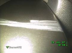
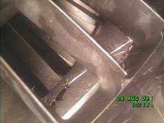
Fig. 1. Evidence of a bird strike
3. Types of
damage
The types
of damage are defined below in alphabetical order.
Arcing is
caused by the inaccurate electrical discharge between an electrode and the part
in question due to inadequate contact. A igniter input terminal well would be a
typical example here. Such a condition is unacceptable, since it may result in
an uncontained discharge.
An arc burn resembles several small circles located on the surface,
which are caused by heat influence. Such a phenomenon may appear on blades,
even at their leading edges, rendering them unserviceable.
Battering is
evidenced by minor surface indentations and the result of constant hitting by
minor objects.
An object is bent when the angular distortion from the original contour occurs.
This damage is typical on leading and trailing edges of engine blades and
caused by a lateral force. Such damage poses more danger to airfoil strength
values than aerodynamics and, as such, bents are sometimes considered as dents
by some manuals. In this scenario, it is to be measured in a lateral not an axial
direction. A typical bend often appears on trailing edges as a result of
foreign object impact. A large-scale bent in various dimensions is called buckling, which is caused by a foreign
object or mechanical or thermal overload. An example of a trailing edge bend,
which is to be investigated as a dent, is illustrated below.
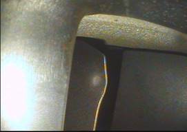
Fig. 2. Low-pressure compressor’s
trailing edge blade bend.
Binding
refers to two adjoining components that rub against each other, which may
result in tightening or a seizure. The reason for this condition may be a
decrease in separation due to temperature changes and/or the different thermal
capacity of materials or a foreign object between affected areas. The rotor
seizure is an example here. Such a condition may occur if the engine is shut
down and requires a cooling period, which has not been observed.
Blistering
occurs as a result of improper bonding between a base material and painted or
plated surfaces, which appears when the surface coating is raised from the base
material. This condition is aggravated by heat, moisture and a contaminated
environment.
Bowed refers
to the impairment of the original shape, either by impact or by influence
extended over time. Contrary to bent damage, bowing involves a larger curved
radius and is caused, for example, by heat rather than a lateral impact.
Brinelling
refers to damage that is typical for bearing races and is the result of a shock
load carried by the bearing, which exceeds material hardness. Brinelling most
often appears during an extended non-operation period of an engine. The load
will cause unacceptable roller or ball distortion. Bearings that are not loaded
evenly will show a brinelling tendency. This condition may also be caused by
inadequate manufacturing and/or assembly. Brinelling results in a groove of the
same size as the balls or rollers of the bearing, while indentation is still
metallic on the bottom.
False brinelling is a sort of fretting corrosion rather than a brinelling indentation,
which looks like straight traces across
the roller or ball, which are caused by a smaller but frequent load. Contrary
to true brinelling, this is acceptable, since it neither causes distortion nor
deteriorates roller or ball values.
Brinelling and false brinelling may
be discovered by careful visual inspection. False brinelling occurs when an
engine is not operated, but transported over long distances.
An element is defined as broken when it has been split into
several pieces, which is most likely caused by an acting force and fatigue.
A bulge is a mild distortion or displacement of the material without
separation due to excessive pressure and/or thermal influence. Wheel tyre
swelling is an example of a bulge.
A burn refers to structural damage due to heat influence with no or
improper protection, lubrication, clearance and shielding, or uneven
temperature spread. It is accompanied by discoloration and, if not corrected,
breaks the flow of material, which means the total loss of characteristics.
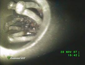
Fig. 3. Chromel-alumel thermocouple
junction burnt.
Burnishing
is a smooth flattening of a surface, with no wear to the material in depth.
Therefore, it appears between surfaces of restrained contact. This condition is
acceptable, provided it does not result in pile-up.
A burr is observed when the material is displaced, but not removed,
which breaks the material flow, causing a sharp edge. This condition may result
from peening, improper machining or foreign object impact.
Carboning
refers to layers of carbon stocked on a material. Fuel nozzles are the parts of
the engine where such a phenomenon most often occurs. This is the by-product of
a combustion process, which is not often perfect. The area of accumulation is
the result of fuel atomization, mixture swirling and low axial flow. Carboning
of fuel nozzles is not a cause for rejection, provided it is not excessive.
Excessive carboning will affect fuel spaying, which will further result in an
uneven fuel/air mixture and stream temperature.
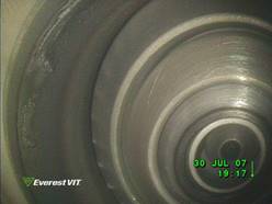
Fig. 4. Minor carboning on the fuel
nozzle
Chafing is
typical description for the abrasion of two adjacent components, if at least
one of them moves in a limited area against the other. This effect is often
discovered between two tubes or pipes if they are not sufficiently separated
from each other.
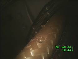
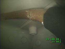
Fig. 5. Chafing between two adjacent
cables due to insufficient separation
Chipping
refers to the breaking away of small pieces under mechanical force, which is
quite often an acceptable condition. This will result in local stress concentration
due to material discontinuity. Contrary to flaking, chipping has a significant
depth.
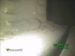
Fig. 6. Chunks of surface coating at
the trailing edge of a high-pressure turbine blade
Crazing is a
net-shaped surface effect, which usually does not pose a danger, provided that
it is not accompanied by a base material crack.
Corrosion is
the result of a chemical reaction on the base material, which is inhibited by a
salty, humid and contaminated environment. Corrosion sharply affects mechanical
strength and causes surface porosity, although corrosion is not always visible
on the external surface. If subsurface corrosion exists, blistering of the
surface coating and/or minor roughness may occur. Corrosion can also be caused
by constant tensile stress when applied to aluminium alloys, high-strength
alloys and some stainless steels. Corrosion appears also when stress is applied
and affects the base material through minor cracks. This is usually caused by
inadequate surface finishing. Galvanic corrosion appears when there are current
flows between two materials of different potential. If corrosion remains
unrepaired, it will develop into exfoliation.
Crack is a
minor fracture, which appears due to excessive abrupt load initiated at the
weakest point of the structure, i.e., nick or gauge. If the crack occurs on the
surface, it may be prevented from expanding by drilling. It is important to
have a smooth surface in order to avoid stresses. The blending of a damaged
blade is an example of such a rectifying method. It restores smoothness to the
affected area and prevents further failure.
A curled object is evidenced by the folding of a rotating part
against its case. This is quite often observed when an axial compressor or
turbine blades rub against the outer case. This effect is unacceptable. During
visual inspection, it is important to check whether the upper half of the rotor
stage is in contact in the case of static conditions.
A dent is a round-bottomed, smooth and shallow cavity, which results
from impact or prolonged constant overload. Material is displaced, but not
removed.
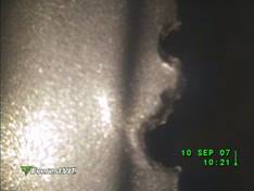
Fig. 7. Dents on a compressor
blade’s leading edge
Distortion is
an unexpected change in the basic contour, which is generally the result of
impact, thermal or mechanical influence or stresses applied to an object.
Erosion is a
reaction on material, which causes it to slowly wear away when exposed to high
temperature, fumes, acids, greases, oils and other active chemical compounds.
The higher the temperature, the faster the reaction. A gas generator module is
most affected by this erosion phenomenon, particularly combustion chambers and
high-pressure turbines. Erosion is also aggravated by massive stream flows and
turbulence.
Fatigue failure is caused by one of the following factors: material inclusions, sharp
edges, nicks, gauges, minor crack or tear, local and/or repeated force. An
excessive force crack is initiated in or near the place of the highest stress
concentration, very often at or near the surface. Fatigue failure occurs due to
repetitive or constant load, while failure will start at the weakest point,
then propagate inside the material. The reason for fatigue cracking is,
firstly, the rubbing of the grains of the material under stress, followed by
mutual battering. Battered and splashed grains set a “flat” surface, which
initiates the crack. Fatigue failure caused by excessive force will occur when
nuts or bolts are over-torqued. This is quite common during aircraft
maintenance; as such, torque application procedures, which are described in the
general maintenance chapter, must be observed.
Flaking is
the disintegration of paint or other external surface due to poor bonding or
excessive load. An example of this deterioration is a when the coating flakes
on high-pressure turbine vanes and blades. Due to high-temperature exposure,
those airfoils are covered by bonding and ceramic coatings, which significantly
increase the operational level of the blade by more than 100°. A bonding layer
is an alloy of nickel, cobalt, chromium, aluminium and yttrium, while ceramic
coating is a zirconia-stabilized yttrium oxide. The bonding layer produces
oxide when exposed to high temperature and is porous enough to accommodate the
outer zirconia layer, which decreases thermal shock on the airfoil. Given the
design of high-pressure compressor vanes and blades, the flaking of protective
layers affects engines’ long-term condition.
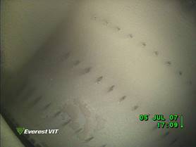
Fig. 8. Coating missing from the
high-pressure turbine blade’s concave side due to flaking
Foreign object
is a common phrase that refers to the situation when there is an element
present, which is not an engine part. The object may loosen freely in the
respective area or be fixed to or stuck in some way. “FOD” is an abbreviation
for foreign object damage, while “DOD” means domestic object damage.
Flowing
refers to the spreading of a plated or painted surface, which is usually
accompanied by blistering and caused by excessive thermal influence and/or
inadequate bonding.
A
fracture occurs when material falls apart into two or more large-sized
pieces. This is caused by an extreme force or coincidence of less significant
stresses.
Fretting is
a kind of corrosion, which results from the intensive rubbing of adjoining
surfaces under a significant load, which results in high-frequency vibration.
Due to the friction of the surfaces, minor particles separate from the
materials, but remain between surfaces during operation mode because of tight
clearance, causing additional friction and pitting. These particles will also
cause the hardening of adjoining surfaces, which may result in stress cracks
over the long term. Fretting, which is aggravated by a humid environment, is
typical for blade platforms and mid-span shrouds. Fretting of aluminium or
magnesium will be visible as a black colour, and as a brown colour on steel
components.
Fretting corrosion is acceptable
only on non-functional areas.
Galling is a
type of damage that occurs when two adjoining materials protrude each other,
resulting in degradation to both surfaces. This happens under high pressure and
relative movement with chafing.
Glazing is a
slight friction between two elements, caused by inadequate lubrication and
under load, which is typical for ball bearings and resembles a circumferential
groove with a well-rounded bottom. Glazing affects machined surfaces on bearing
races and, as such, is unacceptable.
A gouge is a deep and sharp indentation usually caused by improper
handling or sharp foreign object impact. Material is displaced from the surface,
but not removed. The gouge breaks the material flow. With significant length,
it is called a score.
A groove is round-bottom indentation, resulting from the periodic
wear of two parts in mutual motion. The reason may be misalignment or a foreign
object trapped in-between.
Guttering is
an extensive erosion, which takes place over a long time, starting with a
crack, tear or nick exposed to a high temperature stream.
Inclusions
are defined as foreign particles or impurities inside the material. These are
usually flaws, which occur during the manufacturing process. Inclusion may be
localized by magnetic inspection.
A
nick is a groove-like bottom indentation on the surface or edge. Contrary
to a dent, it breaks the material flow and concentrates stress. A nick bottom
may be followed by the crack. While nicks are inflicted by a sharp tool or
other subject impact, they are most often caused by a small, but sharp, foreign
object. FOD or sand nicks are typical types of damage to leading edges of
compressor blades.
Peeling
occurs when the surface finish has broken away.
Pick-up is
an overlaying of material with no depression of the material at the point of
removal. Material from one surface adheres to another surface. This is caused
by the tight rubbing of adjacent surfaces or an excessive axial load on
threads. It will occur when the thread connection is arranged inadequately or
is not lubricated.
Pile-up is
an overlaying of material, which, contrary to pick-up, occurs when material
displaced from the point of removal leaves a depression.
Pitting is
caused by irregular chipping or foreign object influence or may result from
corrosion. This occurs in response to a chemical environment, i.e., exhaust
gases, causing oxidation to the material and forming irregular cavities. A lack
of or poor protective coating will be an inhibiting factor. Mechanical chipping
is caused by overloading and/or inclusion removal in operation mode. The other
reason for pitting may be electrical discharge.
Rupture
refers to damage to a surface, which occurs due to pressure breaking through or
force from inside.
Scoring is
the effect of abrasion, resulting in multiple scratches, when a minor foreign
particle is trapped between two moving surfaces of significant size, causing dragged
indentations and base material removal. Sharp edges in relative motion may also
cause such a phenomenon.
A
scratch is a very shallow elongated indentation with a sharp bottom on the
surface caused by a sharp minor object (e.g., sand) or improper handling.
Contrary to a crack or groove, it has no significant depth.
A shear is discovered when two adjacent surfaces move in opposite
directions.
Skidding is
caused by excessive slipping between two adjacent elements, causing wear or a
frosted surface. The reason for this is poor lubrication and intermittent load.
This kind of damage is typical to silver-coloured ball and roller
bearings.
Spalling is
the excessive chipping of covered surface, which results from the regular
chipping of a covering layer over a long period of time. Area and depth are
more affected by the chipping, which is
most often caused by fatigue crack or another progressive surface irregularity.
Spalling may originate from base material inclusion or any similar defect. Ball
bearing spalling is caused by uneven load on the contact surface, surface flaw
or crack.
A
tear occurs when forces act on a part in perpendicular dimension. Contrary
to a crack or nick, a tear is not enclosed in one plane and observed when
material is pulled apart. Most often, it is caused by the impact of a
significant, tough and sharp foreign object.
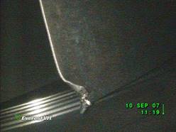
Fig. 9.
High-pressure compressor with a leading edge tear
4. CONCLUSIONS
Most of the above descriptions refer
to engine blades and vanes, given that these are the most vulnerable components
of a turbine engine. The reasons behind these types of damage are specific
working conditions: temperatures up to 1,600°C, up to 18,000 RPM and huge
aerodynamic influence, as fully ducted turbine engines use up to 1,500 kg/s of
air to produce thrust. Furthermore, their condition is influenced by gas stream
contamination and different atmospheric conditions. This means that all the
elements of the duct should be frequently and carefully inspected, since failure
of those elements may result in engine failure or increased overhaul costs due
to unscheduled engine removal.
References
1. Boyce Meherwan P. 2002. Gas Turbine Engineering Handbook.
Houston, TX: Gulf Professional Publishing.
2. Czech Piotr. 2012. “Diagnosis of
industrial gearboxes condition by vibration and time-frequency,
scale-frequency, frequency-frequency analysis”. Metalurgija, Vol. 51, Issue 4: 521-524. ISSN: 0543-5846.
3. Eimantas Juodzevičius. 2011. “The
vibroacoustical research of roll bearings defects”. Transport, Vol. 18, Issue 1: 32-36. DOI: http://dx.doi.org/10.1080/16483840.2003.10414060.
ISSN: 1648-4142.
4.
Lotnicze silniki turbinowe:
konstrukcja – eksploatacja – diagnostyka. Część
I. 2010. Warszawa: Instytut Lotnictwa. [In Polish: Aviation turbine engines: design – operation
– diagnostics. Part 1. 2010. Warsaw: Institute of Aviation].
5.
Madej
Henryk, Piotr Czech. 2010. “Discrete wavelet transform and probabilistic neural
network in IC engine fault diagnosis”. Eksploatacja
i Niezawodnosc - Maintenance and Reliability, Vol. 4(48): 47-54. ISSN:
1507-2711.
6.
Obuchowski
Jakub, Zimroz Radoslaw, Wylomanska Agnieszka. 2016.
“Blind equalization using combined skewness-kurtosis criterion for gearbox
vibration enhancement”. Measurement,
Vol. 88: 34-44. DOI: http://doi.org/10.1016/j.measurement.2016.03.034. ISSN: 0263-2241.
7.
Padgurskas
Juozas, Raimundas Rukuiža, Algirdas Meškinis, Raimondas Kreivaitis, Bronislovas
Spruogis. 2016. “Influence of manufacturing methods on the tribological
properties of rapeseed oil lubricants”. Transport,
Vol. 31, Issue 1: 56-62. http://dx.doi.org/10.3846/16484142.2015.1048525. ISSN:
1648-4142.
8. Rolls-Royce plc. 1996. The Jet Engine. Chichester: Wiley.
9.
Wodecki
Jacek, Pawel Stefaniak, Jakub Obuchowski, Agnieszka Wylomanska, Radosław Zimroz.
2016. “Combination of principal component analysis and time-frequency representations
of multichannel vibration data for gearbox fault detection”. Journal of Vibroengineering, Vol. 18,
Issue 4: 2167-2175. DOI: 10.21595/jve.2016.17114.
ISSN: 1392-8716.
Received 28.12.2016;
accepted in revised form 12.02.2017
![]()
Scientific Journal of Silesian University of
Technology. Series Transport is licensed under a Creative Commons
Attribution 4.0 International License