Article citation information:
Kuľka, J., Kopas, M., Faltinová, E., Mantič, M., Bigoš, P. Kinematic linkages in the hinged undercarriage of a mobile working
machine. Scientific Journal of Silesian University of
Technology. Series Transport. 2016, 91,
81-88. ISSN: 0209-3324.
DOI: 10.20858/sjsutst.2016.91.8.
Jozef KUĽKA[1],
Melichar KOPAS[2],
Eva FALTINOVÁ[3],
Martin MANTIČ[4],
Peter BIGOŠ[5]
KINEMATIC LINKAGES IN THE HINGED UNDERCARRIAGE
OF A MOBILE WORKING MACHINE
Summary. The main purpose of this article is to present a possible description of
kinematic characteristics concerning the direction of travel of a selected
mobile working machine in motion, namely, a hinged loader. This description is
presented in the form of equations, which define the circumferential velocity
as well as the angular velocity of the vehicle wheels during a ride involving a
curve. In this way, it is also possible to describe a function of the axle
differential.
Keywords: hinged loader, kinematic linkages, direction of
travel, riding a curve, travel speed
1. INTRODUCTION
Similar
to other engineering entities, optimization of the design process and operation
of mobile working machines requires the application of computer simulations
based on dynamic models, which are created in relation to real objects.
The
predominant characteristics of the dynamic model, which has to simulate the
real machine, can be determined after the performed analysis of the concerned
kinematic linkages in the given object. The detailed kinematic analysis is often
constrained due to real software and hardware possibilities or limitations.
Therefore, the overarching complexity of the individual design components
of the real machine, including the undercarriage, working equipment and driving
system, cannot be integrated into the created model as a whole [6,7].
Taking
into consideration the above-mentioned conditions, it is also useful to
describe the axle differential function during the vehicle ride involving
a curve by means of kinematic linkages that support wheel rolling without
slippage.
2. DRIVING IN THE DESIRED DIRECTION OF TRAVEL
Much of the worldwide production of
loaders involves the wheeled undercarriage with the articulated framework, such
that the both parts of the undercarriage are jointed by a couple of hinges [1,3].
The position of the vertical hinge
enables mutual turning of the framework parts in the two-sided angular range of
35° to 45°, i.e., it is used to ride a curve.
The horizontal hinge is designed in order to eliminate bending and
torsional moments, which are responsible for loading the framework of vehicle.
As both axles have the same wheel track and the same tyres, the rolling
resistance is reduced.
The mechanism for driving in the
desired direction of travel is specific to the hinged undercarriages, which are
different from undercarriages of the other mobile working machines.
The following are known as driving systems that work with the desired
direction of travel [5]:
o
Manual
driving systems
o
Driving
systems with a servo unit
o
Machine
driving (with an external source of power)
There are many
variants in the construction of driving mechanisms, which are designed in line
with the requirements concerning the precision of the vehicle positioning as
well as the forces that result in loading the undercarriage [8,9]. Individual driving systems are described in [2] and
[5].
The simplest
principle consists of the application of two double-acting linear hydraulic
motors (hydraulic cylinders) combined with a vertical hinge. The axles are
fixed steadily to the individual machine sections.
In the case of direct (linear)
travel, the hydraulic cylinder lengths are the same, while any change in the
hydraulic cylinder lengths causes a mutual turning of both machine sections
around the vertical hinge VK (Fig. 1). A crosswise interconnection of the
working volumes between the hydraulic cylinders ensures the same reaction from
the driving system when turning to the left or the right.
The mutual position of the machine
sections is controlled by the feedback SV (Fig. 1). The feedback can be
arranged using:
·
mechanical
linkage, which is applied to a leverage mechanism
·
hydraulic
linkage, which is mostly equipped with a measuring hydraulic generator
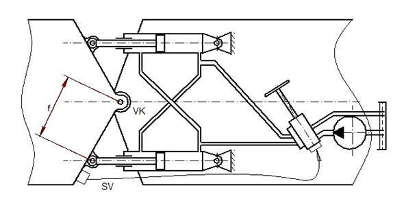
Fig. 1 Scheme of the driving mechanism arrangement
3. KINEMATIC LINKAGES OF TRAVEL WHEELS
Fig. 2 schematically illustrates the driving mechanism, which is
designed to turn the hinged loader by means of linear hydraulic motors
(hydraulic cylinders). The linear shifting of the pistons in the hydraulic
cylinders (piston retracting or pushing out) causes a mutual turning of
the front and rear parts of the wheel loader around the vertical hinge VK.
The scheme in Fig. 2
corresponds to the arrangement in Fig. 1. Meanwhile, Fig. 2 is in effect a simplified
form of Fig. 1.
Curved travel involves
the motion of the vehicle on a curved trajectory around
the instantaneous centre of the wheel loader rotation O1. The point O1 is
a cross-point of the prolonged axles, according to Fig. 3.
Thus, vehicle turning
is caused by a mutual turning of the front and rear parts of the wheel
loader around the vertical hinge VK.
In a case involving
the constant travelling speed ![]() , the circumferential speed of the wheels on both sides of
the vehicle will be different during curved travel.
, the circumferential speed of the wheels on both sides of
the vehicle will be different during curved travel.
If the
circumferential speed of the wheel, which is situated on the internal side of the
curve, is signed ![]() , then the circumferential speed of the wheel rotating on the
external side of the curve is signed
, then the circumferential speed of the wheel rotating on the
external side of the curve is signed ![]() . It is evident that
. It is evident that ![]() .
.
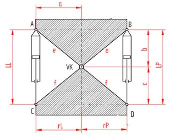
Fig. 2
Scheme of geometric dimensions of a driving mechanism that supports the desired direction
of travel
A, B – positions of turning points for
cylinders in hydraulic motors; C, D – positions of turning points for piston
pins of hydraulic motors; LL, LP – length of the left and the right hydraulic
motor; VK – vertical hinge
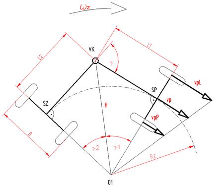
Fig. 3 Curved travel, horizontal
projection
O1 – instantaneous centre of the
wheel loader rotation; SP – centre of the front axle;
SZ – centre of the rear axle; VK –
vertical hinge; L1, L2 – distances of axles from the vertical hinge; B – wheel
track; ![]() – instantaneous
turning radius;
– instantaneous
turning radius; ![]() – angular speed relating to the centre of rotation
– angular speed relating to the centre of rotation
The travel speed of the loader can be expressed
as follows:
![]() ,
(1)
,
(1)
where![]() is the angular speed relating to the centre of rotation,
while
is the angular speed relating to the centre of rotation,
while![]() is the instantaneous turning radius.
is the instantaneous turning radius.
The circumferential speed ![]() of the wheel, which is
situated on the internal side of curve, can then be written in the following form:
of the wheel, which is
situated on the internal side of curve, can then be written in the following form:
![]() ,
(2)
,
(2)
which
means that the circumferential speed ![]() of the wheel on the
external side of curve will be:
of the wheel on the
external side of curve will be:
![]() .
(3)
.
(3)
In the case of the cranked loader
configuration, the turning angle between the front and rear parts of the
vehicle is ![]() (Fig. 3), whereas:
(Fig. 3), whereas:
![]() ,
(4)
,
(4)
where ![]() is the turning angle
of the loader front part, while
is the turning angle
of the loader front part, while![]() is the turning angle at the rear of the loader.
is the turning angle at the rear of the loader.
According to the right-angled triangles ∆(O1,SP,VK) and ∆(O1,SZ,VK), the length of the hypotenuse
H equates to ![]() as well as
as well as ![]() (see Fig. 3).
(see Fig. 3).
By comparing
both relations, which are valid for the value H of the hypotenuse length, the following
equation is obtained:
![]() .
(5)
.
(5)
From Equation
(5),
![]() .
(6)
.
(6)
If ![]() ,
then
,
then ![]() and Equation (6) is
modified as follows:
and Equation (6) is
modified as follows:
![]() .
(7)
.
(7)
Using the goniometric rule, ![]() , Relation (7) can be rewritten as follows:
, Relation (7) can be rewritten as follows:
![]() . (8)
. (8)
After an adjustment of Equation (8),
![]() .
(9)
.
(9)
The relation, which is valid for
![]() , is obtained from (9) above:
, is obtained from (9) above:
 .
(10)
.
(10)
According to Fig. 3, it simultaneously follows from
triangle ∆(O1,SP,VK) that:
![]() (11)
(11)
By comparison the left sides from Equations
(10) and (11), the following relation is obtained:
 (12)
(12)
From Equation (12), the value of the
instantaneous turning radius![]() can be determined:
can be determined:
![]() . (13)
. (13)
From Equation
(1), the following is obtained:
![]() .
(14)
.
(14)
The circumferential speed ![]() of the wheel, which is
situated on the internal side of the curve, as well as the circumferential
speed
of the wheel, which is
situated on the internal side of the curve, as well as the circumferential
speed ![]() of the wheel on the
external side, can be obtained after applying Relation (14) to Equations (2)
and (3), as follows:
of the wheel on the
external side, can be obtained after applying Relation (14) to Equations (2)
and (3), as follows:
 (15)
(15)
 .
(16)
.
(16)
At the same time, it is valid that:
![]() and
and ![]() ,
,
where![]() is the dynamic wheel radius.
is the dynamic wheel radius.
Thus, the values of the angular
speed![]() of the wheel, which is situated on the internal side,
and the angular speed
of the wheel, which is situated on the internal side,
and the angular speed ![]() of the external side
wheel are as follows:
of the external side
wheel are as follows:
 ,
(17)
,
(17)
 . (18)
According to Equations
(17) and (18), a significant difference between the angular speed values of the
wheels rotating on the both sides of axle is evident.
This fact corresponds to the
function of the axle differential of the given wheel loader, whereas Relations
(17) and (18) represent the analytical description of its function.
4. CONCLUSION
This paper presents a
kinematic analysis of driving in the
desired direction of travel in the case of a hinged wheel loader.
The analysis of
kinematic relations, which occur during the driving process, involves a basic
assumption, which is necessary for the creation of the resulting dynamic model
of the wheeled undercarriage for a mobile working machine [4].
Equations (17) and
(18) represent the final result of the performed kinematic analysis of the
loader travel involving a curve. These equations are useful for the next stage of
vehicle travel simulation.
This
paper was elaborated in the framework of the following projects: VEGA1/0197/14 –
research on new methods and innovative design solutions in order to increase
efficiency and reduce emissions of transport vehicle driving units, together
with the evaluation of possible operational risks; VEGA 1/0198/15 – research on
innovative methods for emission reduction of driving units used in transport
vehicles and optimization of active logistic elements in material flows in
order to increase their technical level and reliability; and KEGA 021TUKE–4/2015 – development of
cognitive activities focused on innovations in educational programmes in the discipline
of engineering, as well as building and modernizing specialized laboratories
specified for logistics and intra-operational transport.
References
1.
Dudzinski Piotr. 2005. Lenksysteme fuer Nutzfahrzeuge. [In German: Steering systems for commercial vehicles]. Berlin: Springer-Verlag.
ISBN: 3-540-22788-1.
2.
Kučík Pavol, Igor
Strážovec, Peter Kriššák. 2000. Hydraulický
prenos energie. Mobilné pracovné stroje. [In Slovak: Hydraulic power transmission – Mobile Machinery]. Žilina: EDIS-ŽU.
ISBN: 80-7100-725-0.
3.
Kunze Günter, Helmut
Göhring Klaus Jacob. 2002. Baumaschinen.
Erdbau und Tagebaumaschinen. [In German: Construction. Earthworks and mining equipment]. Braunschweig:
Vieweg und Sohn. ISBN: 3-528-06628-8.
4.
Heisler Heinz.
2002. Advanced Vehicle Technology.
Warrendale: SAE International. ISBN: 9780080493442.
5.
Findeisen Dietmar.
2006. Ölhydraulik.Handbuch für die hydrostatische Leistungs- übertragung in der
Fluidtechnik. [In German: Oil hydraulics. Manual for
the hydrostatic power transfer in fluid technology]. Berlin:
Springer-Verlag.
ISBN: 13 978-3-540-23880-5.
6.
Vaško
M., B. Leitner, M. Sága. 2010. Computational fatigue damage prediction of the lorry
frames under random excitation. Communications
12(4): 62-67.
ISSN 1335-4205.
7.
Sága M., P. Kopas,
M. Vaško. 2010. Some computational aspects of vehicle shell frames optimization
subjected to fatigue life. Communications
12(4): 73-79.
ISSN: 1335–4205.
8.
Konieczny Ł., R. Burdzik,
J. Warczek, P. Czech, G. Wojnar, J. Młyńczak. 2015. Determination of the effect
of tire stiffness on wheel accelerations by the forced vibration test method. Journal of Vibroengineering 17(8):
4469-4477. ISSN 1392-8716.
9.
Dekys
V., A. Sapietova, O. Stevka. 2013. Understanding of the dynamical properties of
machines based on the interpretation of spectral measurement and FRF.
In. 51st International
Scientific Conference on “Experimental Stress Analysis”:
106-112. Litomerice, Czech Republic. 11-13 June 2013.
Received 12.12.2015; accepted in revised form 28.04.2016
![]()
Scientific Journal of Silesian University of
Technology. Series Transport is licensed under a Creative Commons
Attribution 4.0 International License