Article citation information:
Kłosiński, J., Janusz, J. Numerical tests on the FLC system of a crane
model’s slewing movement. Scientific
Journal of Silesian University of Technology. Series Transport. 2016, 91, 51-58. ISSN: 0209-3324. DOI:
10.20858/sjsutst.2016.91.5.
Jacek KŁOSIŃSKI[1],
Jarosław JANUSZ[2]
NUMERICAL TESTS ON THE FLC
SYSTEM OF A CRANE MODEL’S SLEWING MOVEMENT
Summary. In this paper, selected results from
numerical tests on the influence of FLC settings upon the accuracy and quality
of controlling, as well as the settling times, of a crane model’s slewing
movement are presented.
Keywords: mobile crane; numerical
investigations; payload positioning; FLC controller
1. INTRODUCTION
Typically, the swinging of payloads
carried by cranes represents an essential impediment in their work. Moreover,
this phenomenon may also have a direct influence on the safety of operators, as
well as pose a risk to objects in the surroundings of the service area a
particular crane. A proper strategy for controlling a crane’s work movements
can lead to an essential reduction in the amplitude of payload swinging during the
performance of versatile movements [2, 8] and/or after their termination (Fig. 1).

Fig.
1. Scheme of a mobile crane in the course of moving a payload
The application of a control system upon
working motions also allows for an increase in the precision of payload positioning
in the target point of motion, as well as a reduction in the sensitivity towards
distortions. The general principle is that a properly chosen controller has an
essential role to play in control systems. For standard controllers,
establishing their settings also depends on the dynamics of the considered object.
It seems that an application involving controllers, which are based upon fuzzy
logic, could be very beneficial; however, in this particular case, one should
properly chose the structure and the settings of the controller. In the
present paper, we describe investigations in which the settings of the chosen
types of controllers based on a fuzzy logic were analysed, along with their
influence on the precision and quality of controlling as well as on the time when
working motion was performed. The numerical investigations were performed using
the prepared mathematical model of a crane, which was mounted on a vehicle
chassis together with its driving system. The investigations were restricted to
controlling the slewing motion of the rotational bodywork of the crane,
thereby allowing for payload displacement by a chosen (set) slewing angle [1,
3, 7].
2. matHematIc
Model OF the MOBILE CRANE
Within the simulation
investigations, the mathematical model of the crane described in paper [2] was
utilized. It was derived by taking into account the following assumptions:
-
The
bodies of the chassis and the bodywork of the determined masses and inertial moments
were rigid, with six degrees of freedom; moreover, mutual slewing of the bodywork
in relation to the chassis possible.
-
The
support system was replaced by a system of springs; masses of springs were
neglected.
-
Slewing
of the bodywork was conducted by means of a hydraulic drive system driven via a
mechanical gear of determined stiffness; moreover, the stiffness of the jib was
also taken into account (in the direction that was compliant with its slewing
around the vertical axis), while masses and moments of inertia concerning the elements
of mechanical gear were neglected.
-
The
jib was considered as a stiff rod of constant length, known mass and moment of inertia.
-
The
payload was hung from/attached to a non-extensible, weightless and (flabby)
flexible rope, that was wound on the drum of a hoisting winch placed on the end
of the jib; the hanging payload was considered to be mathematical pendulum.
-
Backlashes
and friction, which occurred in the support system, jib and mechanical gear,
were neglected
-
Damping
in the system was taken into account.
-
The
characteristics of elastic connections and damping elements, found within the assumed
intervals in the deflection of elements, were assumed as linear.
-
The
supports were assumed as unilateral, as well as having the capacity to lose
contact with the ground.
The crane model, together with the
model of the driving system, was considered as a controlling object, which was connected
to the controller model of controller equipped with fuzzy logic in order to create
the model of the control system. It is presented as a block diagram in Fig. 2.
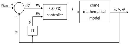
Fig. 2. Functional scheme of the control
system of the mobile crane
In the system under consideration,
we applied a first version proportional-differential (PD) controller, where the
input signals were Dj, i.e., the difference between the value of the
set slewing (rotational) angle of a jib and the value of the current rotational
angle ![]() , as well as being a derivative of rotational angle
, as well as being a derivative of rotational angle ![]() . The controller was assumed to be of the Mamdani type, equipped
with the assumed base of rules and the base of triangular membership functions
[3]. The investigations were performed in relation to different values in
the amplification of input and output signals of the controller. Some chosen
results of the performed simulation investigations are also presented in papers
[4, 5, 6].
. The controller was assumed to be of the Mamdani type, equipped
with the assumed base of rules and the base of triangular membership functions
[3]. The investigations were performed in relation to different values in
the amplification of input and output signals of the controller. Some chosen
results of the performed simulation investigations are also presented in papers
[4, 5, 6].
3. NumerIcAL InVeSTIGATIONS OF
THE CONTROL SYSTEM EQUIPPED WITH FLC CONTROLLER
The numerical investigations were performed
using specially prepared software, based on MATLAB. In the written program, it
was possible to change the amplification of input and output signals of
the controller. The courses of the chosen variables in the model – for the
chosen variant for the values of amplification coefficients w1 and w2, as well as for the assumed slewing angle of a jib –
are shown in the figures below. In Fig. 3, the course of the slewing
motion angle and the controlling signal (generated by a controller) are
presented. In Fig. 4, the trajectory of the payload motion in relation to the motion
of the jib ending is presented.
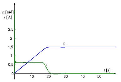
Fig. 3. The angle of rotation j and control signal i
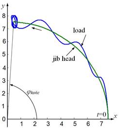
Fig. 4. Trajectories of the jib head
and the payload for control system simulation
These characteristics were used to
determine the time stabilization of motion (achieving an accuracy of less than 5%
of the set value) and the amplitude of payload swinging that remains after the slewing
motion has ended. The relationships for both quantities in relation to the values
of coefficients w1 and w2 are presented in Fig. 5 and
Fig. 6 in the form of spatial charts. We can see that, for some combinations of
w1 and w2, the times of the stabilization
of responses or the amplitude of payload swings, which remain after motion has terminated,
can be sufficiently high that the utilization of these amplifications would be improper
from technical point of view.
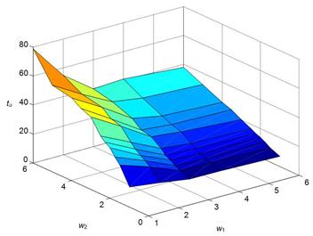
Fig. 5. Diagrams: time regulation tu vs. amplification coefficients of the controller input w1, w2
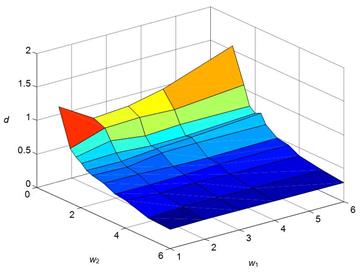
Fig. 6. Diagrams: maximum amplitude of the
payload swings remain after the rotating movement ends vs. amplification coefficients of the controller input w1, w2
The performed investigations also
considered the behaviour of the considered model in the following cases:
a) When operator determines
the value of the slewing motion of the jib (target rotational angle), i.e.,![]() ; then, after a particular time from the beginning of the motion,
the operator changes the decision to increase the target rotational angle (the trajectory
of payload movement for this case is shown in Fig. 7).
; then, after a particular time from the beginning of the motion,
the operator changes the decision to increase the target rotational angle (the trajectory
of payload movement for this case is shown in Fig. 7).
b) When the activity is
similar to that described above, but an operator reduces the target rotational
angle due to changing the decision (Fig. 8).
c) When the activity is
similar to that described above, but the decision about whether to change the
rotational angle is taken by the operator after the set value of the rotational
angle is overcrossed (Fig. 9).
d) When the activity is
similar to that described above, but the operator changes the decision about
the target rotational angle on two occasions (Fig. 10).
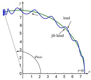
Fig. 7. Trajectories of the jib head
and the payload for control system simulation:
at time t=20s, φkońc changes from
1.5rad to 1.8rad
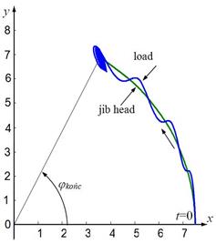
Fig. 8. Trajectories of the jib head
and the payload for control system simulation:
at time t=20s, φkońc changed from 1.5rad to 1rad
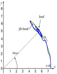
Fig. 9. Trajectories of the jib head
and the payload for control system simulation:
at time t=20s, φkońc changes from 1rad to 0.8rad
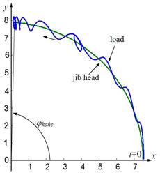
Fig. 10. Trajectories of the jib
head and the payload for control system simulation:
at time t=20s, φkońc changes from 1.5rad to 1rad; at time t=25s, it returns to 1.5rad
4. ConCLUSIONS
Control systems, in which fuzzy logic-based controllers are applied, offer
several advantages:
-
The choice of a controller and the establishment of its setting can be
done without a complete identification of the object of control.
-
Even a proximate
choice of a membership function and a base of rules usually offers satisfactory
quality of control (at least for properly chosen amplifiers of input and output
signals of the controller).
- A complicated imposing function, which controls the system,
does not need to be set on an input of the system.
A disadvantage of the discussed
approach is the lack of possibility in achieving a total reduction in payload swinging
after the termination of movement. It is caused by particular properties of the
object that were applied in the simulation investigations, as well as the static
character of the controller. The model of the mobile crane is an object with a
relatively low level of stability, due to neglecting the effect of damping and movement
resistance, which together result in controlling that is complicated and/or
difficult. The performed simulation investigations have proved that an
application of a different type of FLC controller (e.g., P- type) does not reduce
errors in the positioning of the payload in the end point of the planned
movement.
References
1.
Cho S.K., H.H. Lee.
2002. “A fuzzy-logic antiswing controller for
three-dimensional overhead cranes.” ISA
Transactions 41: 235-243.
2.
Kłosiński J. 2005.
“Swing-free stop control of the slewing motion of the mobile crane”. Control Engineering Practice 13: 451-460.
3.
Kłosiński J. 2011.
“Fuzzy logic-based control of a mobile crane slewing motion”. Mechanics and Mechanical Engineering 15(4):
73-80.
4.
Kłosiński
J., J. Janusz, R. Nycz. 2014. „The impact
of an FLC controller’s settings on the precision of the positioning of a
payload transferred by a mobile crane”. Acta
Mechanica et Automatica 8(4): 181-184.
5.
Kłosiński
J., J. Janusz. 2015. „Wpływ typu i
nastaw regulatora w układzie regulacji ruchu obrotowego żurawia na dokładność
pozycjonowania ładunku”. TTS Technika Transportu Szynowego 12: 787-791. [In Polish: “Influence of the type and parameters of
the controller in the control system of a slewing crane motion on the accuracy
of payload positioning”. Railway
Transport Technology 12: 787-791].
6.
Kłosiński
J., J. Janusz. 2016. „Badania
numeryczne układów regulacji ruchu obrotowego modelu żurawia samochodowego”. [In Polish: “Numerical investigations into the control
systems of the rotation model of a mobile crane”]. In 29th Conference on Development Problems for Working Machines.
Institute of Mechanized Construction and Rock Mining, Warsaw, Poland. 25-27
June 2016, Zakopane, Poland.
ISBN: 978-83-86040-23-0.
7.
Smoczek
J. 2014. “Fuzzy crane control with sensorless payload deflection feedback for
vibration reduction.” Mechanical Systems
and Signal Processing 46: 70-81.
8.
Terashima K., Y. Shen,
K. Yano. 2007. “Modeling and optimal control
of a rotary crane using the straight transfer transformation method”. Control Engineering Practice 15:
1179-1192.
Received 11.12.2015;
accepted in revised form 04.05.2016
![]()
Scientific Journal of Silesian University of
Technology. Series Transport is licensed under a Creative Commons Attribution
4.0 International License