Article citation info:
Krasuski, K. Utilization CSRS-PPP software for recovery aircraft’s position. Scientific Journal of Silesian University of Technology. Series Transport. 2015, 89, 61-68. ISSN: 0209-3324. DOI: 10.20858/sjsutst.2015.89.7.
Kamil KRASUSKI[1]
UTILIZATION CSRS-PPP SOFTWARE FOR RECOVERY AIRCRAFT’S POSITION
Summary. The PPP method is applied in aeronautical
navigation as a new technique for determination of aircraft’s position. In this
paper preliminary results of recovery aircraft’s position were presented. The
raw GPS observations from Topcon dual-frequency receiver were utilized to
position obtained with temporal resolution 1 second. Service on-line CSRS-PPP
was used for estimation vehicle coordinates and receiver clock, troposphere delay
and ambiguity term also. Preliminary results of aircraft’s position show that
accuracy of horizontal coordinates is about 3 cm and less than 7 cm for
vertical coordinate, respectively. The high level accuracy of coordinates is
assured by using precise products such as GPS ephemeris and clocks.
Keywords: GPS, PPP method, positioning
accuracy
1.
Introduction
Implementation GPS technology in
civil aviation is very important for aircraft’s position accuracy improvement.
Especially, GPS technology has got major role during landing procedure on the
airport, without ILS system. New possibilities of GPS receivers, which can
register and collect code and phase observations from triple frequency (L1, L2
and L5), are really in this process. Utilization code and phase information in
GPS positioning find out references in Precise Point Positioning (PPP) method.
Moreover this strategy is very popular on the world and also was using in many
tests of kinematic positioning. In paper [1] NovAtel dual-frequency GPS/GLONASS
receiver was used in the experiment. Rover receiver was installed on the roof
of car and additionally reference station from University of Calgary was
utilized for determination of kinematic position in Double Difference (DD)
solution. Preliminary results from PPP method are very similar to DD
estimation. RMS values for PPP solution are less than 0.161, 0.056 and
In this
paper, CSRS-PPP software in kinematic mode was used for solved aircraft’s
position. The PPP method as a mathematical formulation was utilized in
computations. Observations from Topcon TPS HIPER dual-frequency GPS/GLONASS
receiver was taken in computations, with sample rate 1 s. Firstly results from
CSRS-PPP for presented study are so optimistic. Accuracy of position is about 3
cm for horizontal coordinates and less than 7 cm for vertical component.
2. MATHEMATICAL FORMULATION FOR
DETERMINATION AIRCRAFT’S POSITION
The CSRS-PPP software is on-line
free service, available since 2003 at website:
http://webapp.geod.nrcan.gc.ca/geod/tools-outils/ppp.php?locale=en [7]. The
CSRS-PPP is tool for precise processing of GPS/GLONASS observations in
kinematic and static mode. Currently, application enables for determination, e.g.:
user position, receiver clock, troposphere delay and ambiguity term. The CSRS-PPP
operates as a web interface with limit of data transfer less than 100 MB [8].
Input data in CSRS-PPP is RINEX file and should be send at website, together
with information about user’s e-mail. Additionally mode of positioning
(kinematic or static) should be choice and horizontal (NAD83 or ITRF) and
vertical (CGDV) frame should be mark (see Fig. 1). Moreover, after few minutes
CSRS-PPP tool returns report data on private e-mail address [9]. Report include
4 files:
- „*.sum”− text file with processing
summary,
- „*.pos” − text file with results of
precise processing of kinematic data,
- „*.csv” − text file with coordinates
values for each measurements epoch,
- „*.pdf” − pdf file with graphical
presentation of results.
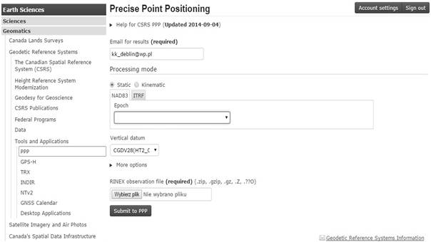
Fig. 1. Interface of
CSRS-PPP software [5]
The CSRS-PPP application utilizes
PPP method for recovery of user’s position. The PPP method based on
„Ionosphere-Free”, which eliminates ionosphere delay on 1st
frequency and instrumental biases DCB from code observations. Moreover, precise
information about satellites coordinates and clocks are applied in
„Ionosphere-Free” (L3) combination, what cause that this combination sometimes
is called PPP technique. From the other side, precise ephemeris and clocks
reduce measurements noise in code observations. What is important, PPP method
enables to estimation user’s position only from single receiver, without
additionally data from network reference stations. This approach is quite
simple and not requires very high price technical infrastructure [10]. Accuracy
of PPP method for static and kinematic mode are very similar to DGPS solution.
In the nearest time, differential techniques will be replaced by PPP method.
Basic equations of PPP method are
given by [10, 11, 12]:
 (1)
(1)
where:
α1=+2.546,
α2=-1.546,
P3, L3− linear
combinations for code and phase observations,
P1, P2− code observations,
L1, L2− phase observations,
d− geometrical
distance between satellite and receiver,
![]() ,
,
(x, y, z) − aircraft position in geocentric frame,
(XS, YS,
ZS) − satellite position in geocentric frame,
C− speed of light,
dtr− receiver clock,
dts− satellite clock,
T− troposphere delay,
T=SHD+SWD,
SHD=MFd·ZHD,
SWD=MFw·ZWD,
MFd, MFw− mapping function for hydrostatic and wet component of troposphere
delay,
ZHD− zenith hydrostatic delay,
ZWD− zenith wet delay,
Rel− relativistic effect,
λ3− wavelength, ![]() cm,
cm,
N3− ambiguity term.
The
aircraft coordinates, receiver clock, zenith wet delay and also ambiguity term
are estimated in sequential process from equation (1). The CSRS-PPP tool set
constraints for presented data in numerical computations, as below [7, 9]:
- positioning mode: kinematic,
- precise ephemeris/clocks: applied,
- reference frame: ITRF,
- ellipsoidal frame: WGS-84,
- satellite antenna phase center
offset: applied,
- receiver antenna phase center
offset: not applied,
- ocean loading correction: not
applied,
- primary meteorological data:
a) Temperature (deg C): 14.33 (GPT model),
b) Pressure (Mb): 947.14 (GPT
model),
c) Relative humidity (%): 50.00 (Default),
- tropospheric models:
a) Hydrostatic delay: Davis (GPT),
b) Wet delay: Hopfield (GPT) initial, but ZWD component is estimated,
c) Mapping functions: GMF,
- instrumental biases DCBP1C1, DCBP2C2:
applied,
- initial receiver coordinates: from RINEX
file,
- pseudorange bias:
- carrier-phase bias:
- cutoff elevation: 100,
- pseudorange: P1, P2 applied,
- carrier-phase: L1, L2 applied,
- interval of calculations: 1 s,
- linear combination: L3,
- number of parameters estimated: k=6.
3. EXPERIMENT AND
RESULTS
The raw GPS observations from Topcon
TPS HIPER receiver were used in the airborne experiment. The Topcon TPS HIPER
was utilized as a rover station and installed in Cessna’s aircraft. Receiver
registers and collects code (P1, P2, C1) and phase (L1, L2) observations from
GPS and GLONASS satellites, with sample rate 1 second. In test, only GPS
observations (P1, P2, L1, L2) were taken from RINEX 2.11 format for
determination vehicle’s position. Flight test was realized in September 2011
year, close to Mielec airport (see Fig. 2 and 3). Time of flight mission was
equal to 3537 measurements epoch, but only 3523 was utilized in computations.
The RINEX file, in primary 14 seconds of flight mission, have got none
observations on 2nd frequency and sometimes number of observations
was less than k parameter (k=6).
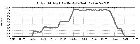
Fig. 2. Vertical trajectory of
Cessna’s aircraft [5]
Moreover, this problem is very
important from flight safety point of view and should be monitored in another
airborne tests. Figure 2 presents vertical trajectory for presented experiment.
Vertical profile in Fig. 2 shows changing of ellipsoidal height in time function.
Maximum and minimum value of vehicle’s height is between about 200 m and
Figure 3 shows horizontal trajectory
in WGS-84 ellipsoidal frame. Vertical and horizontal axes correspond to
Latitude and Longitude coordinates and they are express in meter unit. Primary
and finally point of horizontal trajectory was the same point in Mielec
airport.
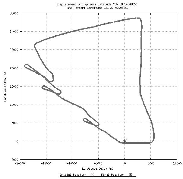
Fig. 3. Horizontal trajectory of
Cessna’s aircraft [5]
Figure 4 presents positioning
accuracy on the background of trajectory differences for each coordinate.
Magnitude of mean errors for latitude coordinate is between
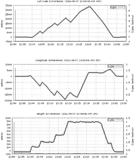
Fig. 4. Accuracy of aircraft’s
position for each measurements epoch [5]
4. CONCLUSIONS
In this
paper, airborne experiment was presented using GPS technology. Aircraft’s
position was estimated in CSRS-PPP software based on PPP method. Algorithm of
CSRS-PPP application was presented and PPP method was characterized. Flight
mission was realized close to Mielec airport and Topcon receiver was utilized
for collection raw GPS observations. Preliminary results of positioning
accuracy show that mean errors for horizontal coordinates are about
References
1. Cai C. 2009. “Precise Point Positioning Using
Dual-Frequency GPS and GLONASS Measurements”. Master thesis. Calgary: University of Calgary.
2. Qu M. 2012. “Experimental studies of wireless
communication and GNSS kinematic Positioning performance In high-mobility
vehicle environments”. Master thesis. Queensland: Queensland University of
Technology.
3. El-Mowafy A. 2011. “Precise
Point Positioning in the airborne mode”. ARTIFICIAL SATELLITES
46(2). DOI: 10.2478/v10018-011-0010-6.
4. Waypoint Products Group. NovAtel Inc. 2006. Airborne Precise Point
Positioning (PPP) in GrafNav 7.80 with Comparisons to Canadian Spatial
Reference System (CSRS) Solutions. Available at:
http://www.novatel.com/assets/Documents/Waypoint/Reports/PPPReport.pdf.
5. Doucet K., M. Herwig, A. Kipka, P. Kreikenbohm,
H. Landau, R. Leandro, M. Moessmer, C. Pagels. 2012. Introducing Ambiguity
Resolution in Webhosted Global Multi-GNSS Precise Positioning with Trimble
RTX-PP. Available at:
https://www.trimble.com/positioning-services/pdf/RTX_Post_Processing.pdf.
6. Gao Y., A. Wojciechowski.
2004. “High precision kinematic
positioning using single dual-frequency GPS receiver”. The International Archives of the
Photogrammetry, Remote Sensing and Spatial Information Sciences 34 Part XXX:
845-850.
7. CSRS-PPP
on-line Service. Available at: http://webapp.geod.nrcan.gc.ca/geod/tools-outils/ppp.php?locale=en.
8. Heßelbartch, A., L. Wanninger. 2010. “Performance
of GNSS-PPP in Post-Processing Mode”. In Hydro 2010. Germany, 02 - 05 November 2010.
9. Nylen, T., S. White. 2007. Online Precise Point
Positioning Using the Canadian Spatial Reference System (CSRS-PPP). UNAVCO.
10. Stępniak K., P.
Wielgosz, J. Paziewski. 2012. „Analysis of PPP accuracy depending
on observing session duration and GNSS systems used”. Biuletyn WAT LXI
(1).
11. Weihing
D. 2004. “Empirical validation of kinematic GPS Precise Point Positioning (PPP)
solutions”. Diploma thesis. Curtin, Australia: Curtin University of Technology.
12. Huber
K., F. Heuberger, C. Abart, A. Karabatic, R. Weber, P. Berglez. 2010. “PPP: Precise Point Positioning –
Constraints and Opportunities”. In FIG
Congress 2010, Facing the Challenges – Building the Capacity. Sydney,
Australia, 11-16 April 2010.
Received 12.04.2015; accepted in revised form 24.09.2015
![]()
Scientific Journal of Silesian University of
Technology. Series Transport is licensed under a Creative Commons Attribution
4.0 International License